When you click on links to various merchants on this site and make a purchase, this can result in this site earning a commission. Affiliate programs and affiliations include, but are not limited to, the eBay Partner Network.
Found this on the GA site. The procedure worked, will test tomorrow as well.
Yeah, I know, I changed two things at once. However, the fan mod was more to be kind to the engine until I can afford a MM Cobb. I need shocks and springs to catch the bigger porches more than power.
To improve the performance of your A/C do the following:
1. Make sure the car is off AND the HVAC fan is off AND the A/C on/off button is off.
2. Press and hold the front defroster (on the left) AND air source (bottom) buttons
3. Continue pressing the buttons in step 2 and turn the key to ACC for 3 seconds
4. Continue pressing the buttons in step 2 and further turn the key to ON (NOT START) for 3 more seconds.
5. Verify the programming update by observing the REAR defroster LED blink 3 times.
6. Release the two buttons from step 2 and start the car.
When you turn on the A/C with the MODE button set to FACE and turn the thermostat to full COLD (max counter -clockwise setting) the RECIRC should automatically engage. In addition, the amplifier should put out colder air (~ 5-10 degrees F colder and not just from the RECIRC setting) and the compressor will not cycle nearly as often (which some of us found annoying).
Note: This programming change is not persistent. If the battery is fully discharged or disconnected the procedure needs to be repeated to re-enable the settings.
(quick note, hold the buttons with your left hand, turn the key with the right)
Hopefully related... I bought a Mazsport cooling fan mod (two relays and a sensor to lower the on temps of the fans. i wondered if I could just plug in one relay from the mod and leave the other to run based on the car's settings. I guess i'd turn the big fan on earlier.
Until today I have never heard the big fan cycling on and off and never had it run after I shut off the car. Today was 95 degrees F and I had some 5 mph traffic and idling. The temp got up to 215 but then was brought down to 207 - I'd like to do that before it gets to 215.
Did this mod last night. Simple and inexpensive for those without an AP. Let the car idle for awhile with the fan switched on and the temp sat right at 175, which is great. Obviously, this will be higher when ambient temps rise, but much better than the 200+ temps I usually see when idling or driving in stop-and-go traffic.
I thought this mod would be great for me here in steamy Louisiana, but don't the fans already come on automatically when the ac is turned on? If I already have the ac on all the time, then this mod would serve no purpose. Correct?
04Green did a great job describing this...but my lame brain had to read it like five times before I understood what he was saying. Here is a pic to help those of you in the same boat as me (bottom of pic is front of engine compartment--the white wire is the one that does the job):
Originally Posted by 04Green
Great Posts, Great Data
Taking the data above, and being too lazy to dig into the harness, I pulled the relay, used a volt meter to find the control side of the relay (the one without 12 volts on it), and soldered a wire (stranded, 20 ga'ish) to that leg of the relay, with the joint in the middle of the pin so as to not mess with the connector, and then ran the wire to one of the bolts that holds the fuse/relay box to the car for a ground. I chose the bolt in the back, because it let me easily run the wire out the same path that the two big power cables came in on. Now, if the car is on, the fans are on low. Car is off, fans shut off in about 10 seconds.
Pending testing, I will likely run this way in the summer, and when it cools down here in Florida, I will probably put in a switch as opposed to cutting the wire. Needless to say, the switch will be on for track days.
Note, on the 04, relay 2 is only active if relay 1 is already on.
Solder instructions.
The relay has 4 tabs that come out of it. Two are copper, and larger than the other two. These are the ones that are controlled. The other two, the smaller ones, are the ones that control. The one you want to solder the wire to is the one towards the front of the car when the relay is installed. The reason I put the wire in the middle, was to make it easy to put in the connector. The reason for stranded wire was that I could make it flat, again to make it easy on the connector. I also filed it smooth when I was done to make it easier to install.
I will update if it works as planned, or if the whole thing catches fire.
/edit/ It is working wonderfully, car has not caught fire /edit/
Mike
Last edited by slideadams; 08-27-2011 at 03:23 PM.
Reason: clarification
Installed a manual ONN/OFF-switch plus seperate blinking LED-signallight today on the tunnel console (aside the seat heater switches), enabling myself to have running the 2 cooling fans at 1/2 speed for additional/preventive cooling when during hot summer running into traffic congestion/heavy stop and go situations the oil temperature is quickly rising.
The posts of StealthTL and slideadams (thanks) were a good help to find the wire at the fan relay 1.
wkr, Ruud
Because it has been over 100F here in the DFW area for the past two weeks and will continue to be (as it usually is in July and August), and because I often sit in stop and go traffic, and because once I reach my subdivision, I have to drive 15mph for several miles as my coolant temps rise, I decided to do this mod to give me more control over said coolant temps.
I removed one of the unused switch plates in the driver's left cluster, drilled a hole in it, and installed a nice looking black rocker switch. I soldered two 20ga Teflon appliance wires to the switch and ran them through the firewall where I had previously created a hole for my subwoofer power wire in the grommet next to the large wire bundle. One wire went to a chassis ground under the hood via a crimp ring, and the other went to relay 1's control terminal. I did not solder it like Green did. I just fanned it, slid it into the connector hole, and pushed the relay in over it. I can always solder it later if I need to.
Both fans turn on low speed when the switch is flipped and stay on after the car is turned off for about 5 seconds.
I am planning to drive my car to work tomorrow and watch the temps while playing with the switch. I will report back with my findings. When I finally reached my garage yesterday afternoon, my coolant temp was 216F for the sake of comparison. It then rose to nearly 222F after the car was shut off. I'm thinking I can turn the fans on any time I hit traffic and when I reach the entrance to my subdivision to cool things down before I get home. This should also be helpful when I exit the track after an insufficient cool-down lap.
The true underlying reason for reviving this thread is to report that the mod works with S2 cars. Of course, I studied the schematic before applying the mod to be on the safe side.
Actually, the nice looking black plastic rocker switch I bought was defective, so I used an ill-fitting mini toggle temporarily until I can find a better rocker.
The new wires are black with red stripes in the lower center area of this pic. I'll tidy those up one the installation is finalized.
Wire runs to relay 1's control terminal, which is on the right side of the relay toward the front of the car.
.
Last edited by Steve Dallas; 08-05-2015 at 11:01 PM.
I hit the switch shortly before I entered my subdivision and ended up a 194F when I shut it down in the garage. That is more improvement than I expected considering that the fans run at some lower speeds any time the AC is on. I need to peruse those rules again...
I soldered two 20ga Teflon appliance wires to the switch and ran them through the firewall where I had previously created a hole for my subwoofer power wire in the grommet next to the large wire bundle. One wire went to a chassis ground under the hood via a crimp ring, and the other went to relay 1's control terminal. I did not solder it like Green did. I just fanned it, slid it into the connector hole, and pushed the relay in over it. I can always solder it later if I need to.
That was pretty smart of you to do it that way ....
Anyone know why thermos would run constantly have installed the rx8 cooling kit mazsport with the two relays attached to wire with ground started car from being cold and they come on with ignition and dont go off untill turn car off about 10seconds after being turned off anyone can help to know why they would run constantly as if the temp sender giving false reading to turn on immediately even though car cold
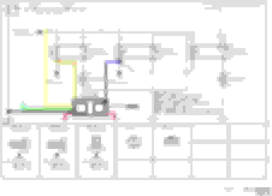
it’s not that difficult really, but after studying the info and diagram below some let us know what questions you may have and it can likely be easily explained
unfortunately text explanations alone often aren’t enough as some people can’t see things as easily in their mind and then pics and diagrams speak volumes more clearly. I posted this up 4 or 5 years ago:
pretty much you can see in the highlighted Mazda information further below what factory strategy and configuration is as follows and as indicated in the top diagram :
no fans - all relays off
fans 1 & 2 run in series for both on in low speed operation - relay 1 on
fans 1 & 2 run in parallel for both on in high speed operation - all three relays on
As demonstrated in the various Relay operating conditions below of which are either off or on. Essentially turning on Relay 3 allows full 12+ Volt battery power to be directly applied directly to Fan 2 (green highlighting) rather than receiving 1/2 of the battery voltage running power through Fan 1 first in series (yellow highlighting - which is why they both run in low speed when Relay 1 is turned on) and then to compliment that Relay 2 being turned on (green highlighting) allows Fan 1 an alternate direct ground path so that it now also runs in parallel to Fan 2 on full 12+ Volt battery voltage to also operate at high speed.
Originally Posted by TeamRX8
for US S1 RX8s Fan #1 is on the RH/passenger side and Fan #2 is on the LH/driver side
Original S1 Fan Control - May have been modified later by Mazda
Seems like Mazda may have revised the wiring along the way, because on my 2005 Fan Relay #2 and #3 are OE wired to always come on together as indicated in the Control System and wiring diagram information posted above, not separate as stated in the OP #1 post.
So that only provides two modes; both fans on at half-speed (Fan Relay #1 Only, both fans run in series off a single 12 V source) and high speed (Fan Relays #1, #2, and by default #3 too sharing the pcm grounding connection with #2, both fans run in Parallel, each with their own 12V source and individual grounding)
Because I just ordered a controller today for $40 that will bypass the pcm control and allow setting Relay #1 to turn on with an adjustable 160F - 210F range and then Relay 2 is default-set to turn on 10F higher than wherever Relay #1 is adjusted to. Will post it up once received and proven out. Essentially all that's required is to mimic the pcm by grounding the relay on/off ground wire. With the ignition key on, the fan relays always receive 12V power and the pcm either allows pin #20 (Relay 1 - R/G wire) and/or pin #19 (Relay 2 - L/W wire, and by default #3 too) to ground and turn the respective relay on OR not ground and maintain the relays in the Normally Off default position. The controller uses a radiator surface temp probe rather than a coolant temp sensor, but the benefit is that the coolant system doesn't have to be tapped into. By bypassing the PCM they will always run by temperature and not turn off by speed. I personally consider that a benefit, but when on it does create some load on the alternator which in theory will have some impact on fuel MPG.
.
OK, for those who don't have a pcm software programming option, here is one way to over-ride the factory radiator fan temperature setpoints. This applies to the OE fans, or also to the FAL420 or FAL490 aftermarket dual fan assemblies assuming they are wired in the same as the OE fans. The particular controller chosen is the Hayden #3654 dual-fan version; paid about $43 shipped for it. It comes setup to directly control two fans, whether they're 2-wire single speed fans or 3-wire dual speed fans. We don't need to do that though. The fans are already wired in and all we're going to do is turn the existing fan relays on/off just like the factory pcm does, by connecting the relay control to ground or not.
The Hayden controller has dual 40 Amp relays and the wiring size matches it, but since we're only connecting the relay control wiring to ground or not, the actual amp draw is almost nothing. We're also using it as a 2-wire fan controller, so the additional orange and blue wire can be eliminated.
To make the installation easier I just cut those large gauge wires back and will instead replace them with 18 Ga. to make the install easier. I also joined the two Red wires since they will both terminate to the same place and put heat shrink tubing over the two unused control wires.
Then all you have to do is install/wire it in as per this wire color-matched diagram. The wire colors in the diagram don’t correspond exactly to where they are on the controller. The diagram simply serves to show which wire color goes where for making the connection:
The way it works is like this; the low speed relay (Orange wire) is controlled by an adjustable temperature setpoint, which is the small pot in the corner with a flat-blade screw. It's adjustable from 160F - 210F. When it comes on the relay will allow the Orange wire to ground through the Red wire, at which point Fan Relay 1 will come on and both fans will operate in series at 1/2 Output Speed. The controller has a fixed setpoint for the high speed relay; it comes on 10F higher than where the low speed relay is adjusted to. When that temperature is hit then the relay will allow the Blue wire to ground through the other Red wire, at which point Fan Relay 2 will come on, and also Fan Relay 3 because the factory wiring is tied together between them. This then allows both fans to run in parallel at Full Output Speed.
The fan turn-off setpoints are also fixed to occur 10F lower than the turn-on setpoints. So if the Low Speed mode is adjusted to come on at 195F, the High Speed fan mode turns on at 205F, then turns off at 195F, and the Low Speed mode turns off at 185F. The Green wire is intended for Air Conditioner clutch on/off wire to turn the fans on when the AC compressor is engaged, but the factory pcm already should handle this. You could instead run it through an on/off switch in the interior and then to a 12V+ source to force the fans on if you wanted to do so.
.
OK, for those who don't have a pcm software programming option, here is one way to over-ride the factory radiator fan temperature setpoints. This applies to the OE fans, or also to the FAL420 or FAL490 aftermarket dual fan assemblies assuming they are wired in the same as the OE fans. The particular controller chosen is the Hayden #3654 dual-fan version; paid about $43 shipped for it. It comes setup to directly control two fans, whether they're 2-wire single speed fans or 3-wire dual speed fans. We don't need to do that though. The fans are already wired in and all we're going to do is turn the existing fan relays on/off just like the factory pcm does, by connecting the relay control to ground or not.
The Hayden controller has dual 40 Amp relays and the wiring size matches it, but since we're only connecting the relay control wiring to ground or not, the actual amp draw is almost nothing. We're also using it as a 2-wire fan controller, so the additional orange and blue wire can be eliminated.
To make the installation easier I just cut those large gauge wires back and will instead replace them with 18 Ga. to make the install easier. I also joined the two Red wires since they will both terminate to the same place and put heat shrink tubing over the two unused control wires.
Then all you have to do is install/wire it in as per this wire color-matched diagram. The wire colors in the diagram don�t correspond exactly to where they are on the controller. The diagram simply serves to show which wire color goes where for making the connection:
The way it works is like this; the low speed relay (Orange wire) is controlled by an adjustable temperature setpoint, which is the small pot in the corner with a flat-blade screw. It's adjustable from 160F - 210F. When it comes on the relay will allow the Orange wire to ground through the Red wire, at which point Fan Relay 1 will come on and both fans will operate in series at 1/2 Output Speed. The controller has a fixed setpoint for the high speed relay; it comes on 10F higher than where the low speed relay is adjusted to. When that temperature is hit then the relay will allow the Blue wire to ground through the other Red wire, at which point Fan Relay 2 will come on, and also Fan Relay 3 because the factory wiring is tied together between them. This then allows both fans to run in parallel at Full Output Speed.
The fan turn-off setpoints are also fixed to occur 10F lower than the turn-on setpoints. So if the Low Speed mode is adjusted to come on at 195F, the High Speed fan mode turns on at 205F, then turns off at 195F, and the Low Speed mode turns off at 185F. The Green wire is intended for Air Conditioner clutch on/off wire to turn the fans on when the AC compressor is engaged, but the factory pcm already should handle this. You could instead run it through an on/off switch in the interior and then to a 12V+ source to force the fans on if you wanted to do so.
.
I Don't mean to be rude but this seems unnecessary. You can just install a temp switch and run that into the two fan relays just like the rx8 performance mod. Your way acheives the same end goal, but with extra wires/relays.
Never saw this reply; it’s not rude at all, just the opposite. You’re absolutely correct *to some degree* that I didn’t fully think it through at that time, but I never installed it for that reason.
Because the controller I proposed using is for running all the fan current through it and thus; overkill for the amperage requirement. As you were wise enough to recognize, the relays already exist that the high amp fan power is run through. So that part of the controller isn’t required at all. All that needs to be done is to engage the fan relay ground engagement prong to ground before the ecu does. Which is very low amperage circuit. So as you suggest in simplified form, we only need a temp switch from the existing relay ground prong and the grounding point to close the circuit at the desired temperature to ground and engage the existing relay.
Which the controller I proposed already provides; an initial adjustable temperature set-point for low speed and a second 10�F higher temperature set point for high speed, and can be used that purpose. The high amp relays can be pulled out of the controller and all the high amp control wires snipped off. Then simply run a wire from existing relay engagement ground plug into the corresponding controller relay prong and the other corresponding controller relay prong to ground. Then the controller will turn the existing fan relays on/off through the controller.
Or as you propose, have a 2-prong temp switch and run the existing relay ground prong to one temp switch prong and the other prong to ground, and then it engages the existing relay at it’s temperature set-point. *The one issue with your proposal is there’s no deadband zone. It could potentially cycle on/off continuously without some sort of controller to provide a buffer when using a simple on/off switch. So either way my feeling is that some sort of controller is needed. However as you likely already know, they’re available cheap on the web with the radiator fin probe included. I didn’t have that foresight at the time to think it through that far and search for just that part.

 05-11-2010, 09:32 PM