
DIY: Side marker with blinker


DIY: Side marker with turn signal
I saw a question a bit ago about someone modifing their side marker lights to also be blinkers. There was a reference to a Mazda6 web site thread: http://forum.mazda6tech.com/viewtopic.php?t=489
Using the information there, and the wiring diagram for the RX-8, I was able to replicate their success on our cars.
What follows is my first DIY, which adds blinking ability to the side marker lights. Note, since this modifies your electrical system, it could cause a fire, something to break, etc, etc... I.e. don't come and bother me if it doesn't work for you or your burn your car!
Also be sure to check your local laws for blinker colors, bulb colors and such. I suspect a white blinking bulb in a white reflector would probably get you a ticket.
Ok, that out of the way, after I did the following mod the behavior of my side markers is now:
Parking Lights on, turn signal off: Side markers on as normal
Parking Lights off, turn signal on: Blinks with the front turn signal
Parking Lights on, turn signal on: Blinks opposite of the front turn signal
Step 1:
Open the side wheel well mud guard. There are 4 silver screws to remove, and two plastic buttons.
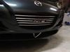
Step 2:
Remove the side marker (I've got clear markers on my car.)
Step 3:
Disconnect the side marker harness from the connector.
Step 4:
Pull out the blinker from the front combination lights (this is REALLY difficult, and easier to do if you have small hands or child who can reach in!)
Step 5:
Disconnect the light socket from the blinker harness. Then cut back the protective tubing so that you can get access to enough of the _GREEN_ wire to splice into.
Using the information there, and the wiring diagram for the RX-8, I was able to replicate their success on our cars.
What follows is my first DIY, which adds blinking ability to the side marker lights. Note, since this modifies your electrical system, it could cause a fire, something to break, etc, etc... I.e. don't come and bother me if it doesn't work for you or your burn your car!
Also be sure to check your local laws for blinker colors, bulb colors and such. I suspect a white blinking bulb in a white reflector would probably get you a ticket.
Ok, that out of the way, after I did the following mod the behavior of my side markers is now:
Parking Lights on, turn signal off: Side markers on as normal
Parking Lights off, turn signal on: Blinks with the front turn signal
Parking Lights on, turn signal on: Blinks opposite of the front turn signal
Step 1:
Open the side wheel well mud guard. There are 4 silver screws to remove, and two plastic buttons.
Step 2:
Remove the side marker (I've got clear markers on my car.)
Step 3:
Disconnect the side marker harness from the connector.
Step 4:
Pull out the blinker from the front combination lights (this is REALLY difficult, and easier to do if you have small hands or child who can reach in!)
Step 5:
Disconnect the light socket from the blinker harness. Then cut back the protective tubing so that you can get access to enough of the _GREEN_ wire to splice into.
Last edited by fray; Aug 15, 2006 at 05:36 PM.
Step 6:
Strip the green wire back so you can splice into it.
Step 7:
Splice in a new wire. It's best to use a colored line here instead of black since this is a positive wire when the blinker is on.
Step 8:
Solder the splice.
Step 9:
Measure the red wire so there is enough wire to go from the blinker connector (when in it's normal position) down to the connector for the side markers. Get some heat shrink tubing and cover the wire as a protector. (This area gets wet and may get engine heat. Everything else in the car is protected by heat shrink tubing.)
Step 10:
Leave enough of the new wire exposed to strip so you can solder to the side marker wire.
We now switch over to the side marker wiring harness.. This is the bit between the connector and the side maker. It contains the bulb socket.
Step 11:
Dissassemble the connector. Use a small screw drive to release the pins and pull them out the back.
Step 12:
Cut one of the wires off.. Do it about 1/2 - 3/4 of an inch from the connector. Then tape up the small bit so that it won't get wet or corroded.
Step 13:
Strip the other end so that it can be connected to the wire from the blinker.
Step 14:
Solder the the wire from the blinker and the black wire. (Be sure to have the heat shrink tubing installed before you solder it.)
Step 15:
Start at the side marker and tape up the solder joint, and tape the heat shrink tubing to the wire harness. Be sure to do this to keep out any water or debris.
Step 16:
Continue taping up the connection, now tape the solder joint on the blinker harness, tape up the tubing you had to cut to get access to the green wire, and finally tape up the heat shrink that protects the new wire.
Step 17:
Double check that everything is taped up. Now place the (empty) connector for the side marker harness to the plug. Match the sides to the wires. One side should be black w/ a red stripe, the other side is just black. The little wire stub from step 12 goes to the side with the black wire. The wire from the side marker light goes to the black/red side. (Don't worry, if you mess this up it'll be easy to diagnose and fix!)
Step 18:
Put the wires back behind the mud guard. Make sure nothing is rubbing or will bind up on anything. Place the bulb where it belongs. Now is the point to test everything:
1) Turn your car on (don't have to start it)
2) Turn on your signal light for that side of the car. Both the front and side marker should blink together.
3) Turn on your parking lights. The front and side marker light should now blink opposite of each other.
4) Turn off your signal light (leave the parking lights on), the side marker should remain on.
If 3/4 do not happen, you reversed the wires to the side marker connector. Double check this connection. Cut wire to black, wire from harness black/red side.
Step 19:
Finish putting everything back together...
Now go and do this to the other side of your car.
Now go an enjoy your side marker blinkers.
Last edited by fray; Aug 13, 2006 at 09:49 PM.
I couldn't figure out the magic to putting the images inline. Anyone have any pointers? 
Otherwise, the pictures above are all in order of the steps.
The theory for how this works:
The side markers when off:
Black - GND
Black/Red - GND
Blinkers when off:
Green - GND
Black - GND
Side Markers when on:
Black - GND
Black/Red - +12
Blinkers when on:
Black - GND
Green - +12
This mod connects the side marker bulb to the Black/Red of side marker harness and the green of the blinker harness. When both the blinker and side marker are on, +12 is on both lines and the light goes out. When either the blinker or side marker is on, there is +12 on one line, and GND on the other.
Last edited by fray; Aug 14, 2006 at 11:41 AM.

the stig is my hero
Joined: Feb 2006
Posts: 701
Likes: 0
From: NC
Thanks for the thorough instructions man. Just as a shortcut for people who have wired before, here are my truncated instructions:
1. Unplug turn signal socket and side marker socket
2. Splice wire onto green turn signal wire
3. Connect spliced wire to side-marker socket wire corresponding to solid black wire before the socket.
4. Dance.
1. Unplug turn signal socket and side marker socket
2. Splice wire onto green turn signal wire
3. Connect spliced wire to side-marker socket wire corresponding to solid black wire before the socket.
4. Dance.


Originally Posted by truemagellen
Will this install be a problem with LED bulbs and load equalizers?
You need to have LEDs that don't have a fixed + and - side. You can double check this by taking out the LED, reversing it in the socket. If it still works then it should be fine.
You can also hook this up temporarily without actually cutting any wires to give it a try as well. Thats what I did when I was developing this, but I have bulbs.
--Mark
You can also hook this up temporarily without actually cutting any wires to give it a try as well. Thats what I did when I was developing this, but I have bulbs.
--Mark
Originally Posted by fray
You need to have LEDs that don't have a fixed + and - side. You can double check this by taking out the LED, reversing it in the socket. If it still works then it should be fine.
You can also hook this up temporarily without actually cutting any wires to give it a try as well. Thats what I did when I was developing this, but I have bulbs.
--Mark
You can also hook this up temporarily without actually cutting any wires to give it a try as well. Thats what I did when I was developing this, but I have bulbs.
--Mark

You could rig up two bulbs to defeat this symptom
or wire in a relay for the side markers.
Or even easier if a person just put a standard bulb in for the side marker.
Last edited by BoosTED; Aug 25, 2006 at 06:55 AM.
Just a quick note about polarity with the way this works:
Black - Red/Black
Side Markers on:
- +
Blinkers on:
+ -
Side Markers on + Blinkers on:
+ +
Side Markers OFF + Blinkers OFF:
- -
Black - Red/Black
Side Markers on:
- +
Blinkers on:
+ -
Side Markers on + Blinkers on:
+ +
Side Markers OFF + Blinkers OFF:
- -

Registered Lunatic
iTrader: (1)
Joined: Aug 2003
Posts: 3,591
Likes: 49
From: SF Bay Area, California
Just a word of caution for those who want to do this mod... I tried to do it yesterday and it's a pain. Reason being that (at least in my case) the turn signal wires are quite a bit shorter than what this picture suggests. So I had almost no space to work and couldn't do a clean splicing. It would be probably easier if I could also detach the plug that goes to the HID bulb, and then pull the whole harness up towards the engine bay to do the splicing there. Problem is that the damn HID plug is so hidden that I have no easy way to find (or even properly feel) the tab that needs to be pushed and just gave up on the whole thing.
It is amazing how tight the space is everywhere around these bulbs and sockets.
Just to give you an idea, if you ever replaced the small 194 bulb on the passenger side that is in the front combination light towards the middle of the car - multiply the PITA factor by 10 and you start to have a feeling how hard it is to get proper access to do this mod. At least IMO...
Maybe if I feel like doing it again, I'll be better off by removing the wheel and peel back the inner splash guard almost completely, then I can get better access.
Last edited by Tamas; Sep 17, 2006 at 02:18 PM.
When I did it, I did it with the wheel on. If you look at the picture you referenced, I had cut the factory wire cover to expose more wire (it's just heat-shrink tube that hasn't been shrunk yet.). I was able to pull it down and into the wheel well and did my splicing inside of the wheel well. Once I spliced it, I used some good quality electrical tape and taped up the part of the cover that I had cut.
It's definatly tight, but it's doable. The key is to make sure your wheel is turned the right direction to give you as much room as possible with the splash guard pulled back.
It's definatly tight, but it's doable. The key is to make sure your wheel is turned the right direction to give you as much room as possible with the splash guard pulled back.

Resu Deretsiger
Joined: Feb 2004
Posts: 369
Likes: 0
From: United Kingdom, for now
Fray -- Thanks for the DIY. Really helpful. I was underneath already to change out some bad foglight bulbs, and decided that since I was there...
All I removed was the bottom half of the fender well liner, and folded up the top half. Wheels on. Only thing I did different: I didn't see the need to disassemble the side marker wires from the connecter. There was enough room between the bulb and the pins to splice the additional wire. I'm happy with the install, all and all. Thanks again.
All I removed was the bottom half of the fender well liner, and folded up the top half. Wheels on. Only thing I did different: I didn't see the need to disassemble the side marker wires from the connecter. There was enough room between the bulb and the pins to splice the additional wire. I'm happy with the install, all and all. Thanks again.
Just completed my sidemarker with blinker (I have LED turn signals with the load resistors in the rear of the car).
No problem with the LEDs as long as they are not a single led (wouldn't be very bright). Not sure about the sidemarker LEDs though since I have incandecent. From what I read at the 6 forum as long as it is a 6 array and not a 4 a person should be fine with LEDs in the sidemarkers.
I cut above the sidemarker disconnect after I checked the colors on the bottom side of it.
The wire to cut above the disconnect (is black below the disconnect).
The other way confirm is with a testor. The line to cut is the ground when the sidemarker is on.
After it is cut then the sidemarker side is spliced in with the Green/black from the turn signal.
What this does is pulls the ground from the turn signal when it is off and loses the ground when the turn signal is used (both lines to the sidemarker get positive signal). So it goes off and on.
:( traded in my 8
Joined: Jul 2005
Posts: 319
Likes: 1
From: Ft Sill OK
ok, I'm no electrical genius but why aren't you using wire taps instead of stripping the wire and soldering in another wire?
Also, can someone please dumb this down a little more, I have read this through 5 times and still can't quite figure out what color wire from the turn signal gets tapped into what color wire on the side marker. Where exactly do you cut the ground. I know.. it is some hand holding but I would appreciate any assistance you all can give.
Thanks.
I used wire taps and wrapped electrical tape around them to help prevent corrosion.
Dumbed down:
Cut the side marker ground (negative when sidemarker is on) (black below the disconnect)
Splice to the green/black (positive) of the turn signal.
What this does is gives the sidemarker power the same as the blinker when the parking lights are off.
When the parking lights are on it takes power away because it gives two positives...
:( traded in my 8
Joined: Jul 2005
Posts: 319
Likes: 1
From: Ft Sill OK
I feel like a dumbass.... Is this what you mean or am I way off base?
Originally Posted by 4 years to Supercharge
I used wire taps and wrapped electrical tape around them to help prevent corrosion.
Dumbed down:
Cut the side marker ground (negative when sidemarker is on) (black below the disconnect)
Splice to the green/black (positive) of the turn signal.
What this does is gives the sidemarker power the same as the blinker when the parking lights are off.
When the parking lights are on it takes power away because it gives two positives...
Dumbed down:
Cut the side marker ground (negative when sidemarker is on) (black below the disconnect)
Splice to the green/black (positive) of the turn signal.
What this does is gives the sidemarker power the same as the blinker when the parking lights are off.
When the parking lights are on it takes power away because it gives two positives...
Yes, your picture is the end result. -- Green/Black tapped going to the ground wire of the side marker. (If you hook it up to the wires between the bulb and connector, and wire it backwards then all you have to do to fix it is pull the wires out of the connector and re-insert them in the opposite holes.)
As for why I soldered vs using a wire tap, the location that the wires are in can get wet. Wire Taps have a nasty habit of failing when they get wet. (Two dissimilar metals oxydizing... copper and steel.)
If you do use a wire tap, make SURE you wrap it and get it water tight!
As for why I soldered vs using a wire tap, the location that the wires are in can get wet. Wire Taps have a nasty habit of failing when they get wet. (Two dissimilar metals oxydizing... copper and steel.)
If you do use a wire tap, make SURE you wrap it and get it water tight!
Originally Posted by fray
I've seen both Aluminum and Steel. Same problem though, dissimilar metals and wetness with the possibility of increasing oxydation.