When you click on links to various merchants on this site and make a purchase, this can result in this site earning a commission. Affiliate programs and affiliations include, but are not limited to, the eBay Partner Network.
I really don't think anyone else would attempt something as ridiculous as this. I think it's safe to say that you and harlan are alone with this type of thing.
Your right, going back I would tell just about anyone not to do it, but I am still driven to see if it has any improvements to the ignition coils or starter. If it doesn't I am going to write it off as a waste of time and smash some florescent light bulbs while pretending I am a Jedi.
Ok, did a couple test cells on this one and found a serious issue unknown to me from before. Charge rate on these does not follow what I would consider making sense for normalize electric charging rate or current flow.
with 6 capacitors, number 2,4, and 6 overcharge ALOT to almost 2.8v/2.5v with 14.0 from a high current charger. Even with my Safety circuit of a switching diode and an LED, they came on very quickly. After reaching 12.7 I got scared and pulled the current source and let the cap bank sit for 4 days. The LEDs are still on for 4 and 6, which is concerning to me. I am thinking for the 350s I need to burn test them by charging and discharging each cap a few times with some kind of Automated break in process to normalize them to each other.
What this means for anyone else is, I would stick with at least 150F total capacitance, because 58 is just unpredictable without active capacitor balancing. If space isn't an issue the typical 3000F/3500F at 2.5/2.7 would be for you. The new 2.85v would be even better! (you would only need 5 of those and the balance to go in between.
So I am building a little test cell to charge all these up at a fixed rate, discharge them slowly, and recharge them a few hundred times with a simple arduino setup.
For the main system I am going to limit the current coming from the alternator, but not limit the current coming from the caps to the starter. I may possibly run a line from the caps in the back to the starter itself and leave the existing wire from the battery post to the fusebox using it as a junction point to a small battery and cap setup. I think the PCM need some kind of power supply itself in case the power drops and the NVram is lost.
The big question is why? A cap is not a replacement for a battery not matter what you put into the circuit. I can understand trying to smooth out voltage a bit as I would with prior IT set ups in industrial vehicles, however the stock systems are designed to have a bit of leeway in voltage parameters. If you are looking for weight savings run a small AGM battery paired with a big *** cap so you still get the on demand amps.
The big question is why? A cap is not a replacement for a battery not matter what you put into the circuit. I can understand trying to smooth out voltage a bit as I would with prior IT set ups in industrial vehicles, however the stock systems are designed to have a bit of leeway in voltage parameters. If you are looking for weight savings run a small AGM battery paired with a big *** cap so you still get the on demand amps.
You are right a cap is not a replacement for a battery. A supercap is not either, it is a better use of Temporary energy storage with less resistance. It also has a much larger temporary output over a longer range of voltage, at the cost of total storage capacity. A supercap, is not a capacitor as you would think it. I wish they called them something else because it leads to a lot of confusion.
I have a flatplate AGM currently and I am not really happy with it to be honest.
So the problem is the circuitry, intelligence and longterm storage. In reality a Lithium Polymer battery with enough power to recharge the cap per start cycle, (cycle being the duration from when the starter.) I have no problem trying to figure out how to do that, even if it turns out to be a waste, which is sort of has.
So why? To free up the alternator for generating a higher voltage for the spark plug, reducing load, and possibly for the electric supercharger if I can ever figure out that ****. If not, the load is reduced and the voltage is higher.....so that can't possibly be a bad thing really...
Last edited by badinfluence; Nov 7, 2015 at 07:34 PM.
Freeing up the alternator will not create a higher voltage spark. Reducing the load may help alternator longevity but that does not seem to be a problem with these units. The amp draw from a proper electronic supercharger would be to much draw on the alternator and would have to be tied into an alternate system.
I know my friend Brad Edwards from austin, dont know his name on the club had a custom super high output alternator built for him that would better suit your needs. I can find out and get back to you if you want.
It will, but not in a way you would think. (I am not trying to get 16v like a drag car, just the 14v the PCM shoots for instead of something like 12.8-13v) If you are genuinely interested, I can show you more about what I am doing with this one, I just publish almost nothing since either no one gets it or I get just a bunch of discouraging feedback on par with a car forum.
The battery wants to rest at 12.7 volts,(8-12OHM) which is why it realistically will never break 13 where as the cap will keep going till the PCM cuts it off at 14. (and would keep going to realistically they would fail and/or explode at 16-17v)(0.009OHM)
I am not really looking for a higher voltage spark, just consistency with the coils trying to keep them alive, lower voltages make that transformer work harder and draw more power at the cost of EMI and noise, whereas if the voltage on the low side was higher, the transformer can do a better job at making a consistent spark.
I also sometimes wonder how much power that EPS really uses.... I feel like in traffic it would be almost nothing, but on a track or twisty if it would be a larger drain.
Realistically I do not want to go any farther without getting some reliability and consistency following the rule mods dont fix existing problems and not to mod a problematic car. I wouldn't call my car problematic, but I would call it ready either. It is also a great car, and I want it to be at 100% of what Mazda wanted it to be since they did such a great job on the R3 in my opinion.
That Electric supercharger maxes out at around 21KW I think. It will never run at full tilt, and it is only to get more low end below the rotary's power curve. I budgeted 7.5KW,(1-7PSI) but that isn't the right way to look at it because it needs to be addressed in Watt Seconds not Watt hours since the supercharger will only run for a series of seconds. I just need to have enough left in the Alternator (20-40a) to charge a series of caps separate from the mains one for a re-configurable power bank and to charge some LIPOs for power conversion. I have been doing math for a year trying to figure out how much power I need to convert and what I need to convert it with. It if ends up not working for the RX8 I really won't mind, it is it's own thing really, and it is a tall order for an electric system.
The alternator is pretty damn good for an OEM at 1440W, but upgrading it isn't a bad idea. The only thing a bit confusing is I think they are called Phase drive alternators? since they are governed by a PWM signal from the PCM. You can actually change that table and force it to increase the voltage, but I don't think that is a good idea without changing the wiring on the alternator to pass through a voltage consistent device. The thing that does worry me a lot of how hot that alternator must get in that engine bay.....
This is the battery I went with btw. For anyone else reading this, go with Odessy. There is nothing wrong with this battery, but the odessy batteries have better performance and even with the smaller batteries are better for relocation mods and are just overall better. I bought this battery immediately after I got the car from the stealership since they just tossed a 26 in there, didn't tie it down, and gave zero ***** about the christmas show going on, on the dash..... So I wasn't thinking relocating it.
Last edited by badinfluence; Nov 9, 2015 at 11:20 AM.
Yeah an Odyssey is what i'm running and suggest as well, just most are not willing to pay. Running a series of caps along with a battery in theory should allow the system to cope with the startup draw of a electronic SC setup.
I had no clue one could change the output voltage on the stock alternator, normally that is something that is hardware related and separate from output control. I have seen a pot adjustment on some high end mil spec units but that is factory set and not something meant for the end user to adjust.
I'm not dissing your idea for getting more spark but man, their are easier ways to do it. I can think of at least three vendors on this forum that sell a kit to do just that.
I'm not dissing your idea for getting more spark but man, their are easier ways to do it. I can think of at least three vendors on this forum that sell a kit to do just that.
Which ones are you referring to? Like engine management ones or physically better coilpacks?
I am running the raceroots setup, and I knew more about it I could change the dwell and ignition characteristics, but as far as other EMS modules for ignition, lots of them have dried up and I thought the consensus was don't do it.
Did some reverse engineering on the cap off the car. There are some issues I have with it....
-The + and - terminals are 11/32 from each other, and I confirmed there is NO circuit protection from shorts or overvoltage. However, there is a REAL balacing circuit that Maxwell themselves uses, which is a opamp on each cap that shorts to the next cap until the voltage is the same accross all 6 caps. It does NOT stop at 2.75 it will keep going till things go boom!
-The terminals are only big enough for those oversized 4AWG connectors that I very much dislike because the fork terminals are the weak point and snap off easily as I have found. They are much bigger than yellow terminals and very uncommon to find. The solder pads are on opposite sides of the board so + on the top - on the bottom.
Here is what I plan on doing to this second cap before I put it on the car in the next few days
-Add over-circuit protection via a isolated power supply & uC.
-Move terminals to opposite sides and use the opposite side for a hardwared 4AWG wire, effectively giving me the ability to have 4AWG cables or a 4AWG and whatever fits on the screw terminal. \
-Build an enclosure (optional)
-Add a charging circuit using the added uC
-Hopefully use the Particle Photon and have this work off WiFi so it can send a push notification if the battery is low and the charger is not working.
-Control the voltage the cap sits at and try and get things stabilized.
-Add a battery isolator so the battery isn't in the circuit when it is not needed. (This has to be custom designed as the great ones on the market don't work for what I am trying to do here. Otherwise a boat/car audio/RV one would be great for 40 bucks.
So far I have
-Removed the terminals and extended the pads scratching away the PCB surface on both sides.
-Remove some hot melt glue which was a BITCH to get off the terminals without ******* up my iron tip. (800 degree tips develop this black **** that doesn't come off without scratching, but the 700s dont do this at all. Frys doesn't sell the PTD7! only the PTD8 for the TC201 Irons.)
-Redesign the battery connection mechanism for the trunk because I have a bad + terminal and the car is throwing B1392? It even knows the + terminal is the problem somehow! Pretty cool Mazda.
-Test how long it takes for the lights in the car to drain the primary cap.... (7 minutes with the trunk and interior lights and with AKE near the car.)(AKE is my problem for the cap and usually isn't on the kind of cars people do the cap mod with)
Next Steps
-Create the Opamp circuit
-Buy ADCs for measuring
-Isolate Power Supply
-Added uC and program it (by far the longest step....)
-Add Opamp backups and overvoltage protection and/or drains....
-Solder 4AWG terminals and add in isolator and cap wiring. (expect so many burns after last time I had to do this. Anderson terminals almost need a MAP torch to melt properly and stay liquid)
My magic lightcube I made for my lab desk. It looks dark, but it is brighter than an HID and each LED is configurable via a 16 key keypad. I normally leave them all on, but if I need something precise I turn on the 3 LEDs in the corner of the cube and go row by row after that.
Like shorting your battery with a wrench, but at 0ohms instead of 12! ****. People use these caps to weld, so that is WAYYYYY to close, better redesign!
I have the BQ33100 IC from TI to balance 5/6 of the caps and some specialized brand new tech from Analog Devices for anything left over.
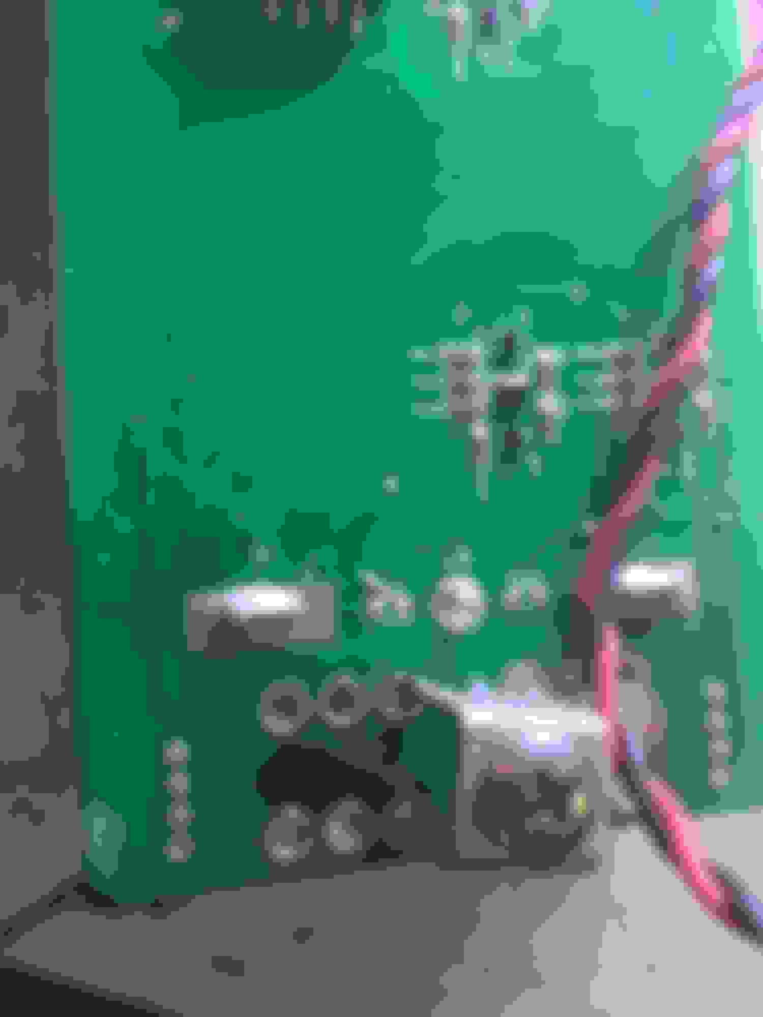
This is the P-Channel-Trench Fet balancing circuit which is function as soon as I properly size the resistors. The top of the TO-220 is where the positive of the Caps connect instead of the middle pin.
On the protoboard is the BQ33100 with an SMD adapter till I can work Eagle better and etch a custom board. Also that is a current meter board in the middle and the initial P channel Trenchfet that is not board of the BQ's circuity, but a bypass for positive voltage back to the car from the alternator.
That light cube is pretty sick. What kind of current meter is that? The package looks huge, I've only ever used sot89.
The light cubes flaw is mounting at the moment. I control it with a 16 digit keypad, an ATMEGA328, and a big *** buck converter with 2 supercaps since it ramps up like a ************ when at 100% white.
Each 1-9 goes to a sector on the 64 pixel cubes with each cluster being 4 pixels and the middle being 4 pixels leaving a tick-tac-toe in the middle off. I considered making a light cube safe and making combinations turning on the whole cube to open something or spit out a code to ASC for a pc like a password remember-er, or make a pretty cool rubix cube. With everything else, I avoided that project since it would just more distraction than the original project.
(The Current Sensor)
I got them from Pololu which make the Zumo robot. I build a few for fun, but I dont understand the digital function of the encoder or current sensor. They use 4 different kinds based on what range you want. https://www.pololu.com/file/download...?file_id=0J196
Allegro ACS714 in the SOIC 8.
I am running the -12.5 to +12.5 amps since a the cap can charge and discharge at the same time, giving power to the car as well as taking power from the alternator. I think I am going to need something more like 50-200amps, but it looks like Pololu have a -75/+75, and as long as it can survive a 200+ amp surge for a few seconds while starting, it would be ideal.
I am a fan of Adafruit and Pololu and they tend to carry each other's products. Being a newbie to the whole IOT/AIC world it is helpful to get all the data both seem to provide.
On an update to the thread, I have laid out what I could call a "module" for multiple projects including this one.
-6x or 5x Supercap Pack with 6S Lipo Connector or 8S if Isolated 5v VCC/3.3 is included or required. (Isolated DC to the DC 9-32v, 1000V isolation 5v 1.5-2a TDK module)
-BQ33100 (Hopefully SMBUS via a Particle Photon running on Isolated VCC 1)
-TrenchFet Pack
-Remote Cabin Module in a Altoids Mini Tin, Passive balancing LED +Switching diode system, but remote in the cabin not at the caps themselves. Also on that same module LED readouts with a switch to monitor each cap and the total system voltage. XPrototab with gates or switches to look for problems. (Since the LCDless version is so cheap), Particle Photon, LCD that will fit on the face of the Tin, and a disable switch per pack (1-8 possible)
-Main Board or motherboard that holds separate modules
--BQ33100 Board
--Switching Charger Converter
--TrenchFet board (Different possibilities for the resistor bleeding between fets)
--Isolated Power Board and Communications Board (Combined)
--4 Slots for Standardized Daughter Boards
--Cap module itself with built in ADCs per cap, Isolated SPI Module (6000v), Mosfet, Diode (1000a), voltage display, integrated Isolated Power module(1205s not the same as the other module), ATTINY84 or ATMEGA328 watchdog, Optofet, and Anderson PowerPole or SB175 Connector
--Alternate Recharge Controller for Solar Panels or energy harvesting from whatever power I have on me at the time. (aaa-D batteries, Cell phone power back, car battery, lithium cell, etc) It will be between 100ma and 1amp and will dump into a TI controller IC designed to work with the BQ33100 at 300ma, but balanced and stable.
This module will be compatible with a Heathkit ET-3X00 Experimenter that I am working on modernizing and creating a portable lab I can take with me and/or have in the living room while watching movies or etc. Because I am doing them at the same time, I think it makes sense to use the same standards. The Experimenter is meant to have the ability to stay powered while you move from place to place as well has generate large power conversions that a switching power supply may not be able to do with a moments notice.
I am finding that the BQ33100 isn't the best documented IC, and SMBUS is a little wacky to try and talk to over I2C, and it may be annoying to try and get it to display things via the LCD.
@badinfluence Here I am finding this thread almost 5 years later. I'm not experiencing any (percieved) problems on my '10 R3, but what you did sounds fascinating. Did you make further progress after the last comment? Did you settle on a final version? How has it behaved since?