Drive By Wire Throttle Wiring Question


Thread Starter
Go Texas Longhorns!
Joined: Apr 2003
Posts: 1,818
Likes: 1
From: Houston, Texas
Drive By Wire Throttle Wiring Question
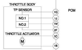
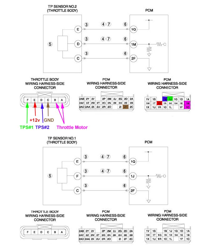
looking at the service manual, it apears that there are 6 wires connecting the PCM to the Throttle Body Control. From the wiring diagram and the service manual, it appears that there are 2 wires that send the signals to the TB to control the throttle plate. the other four are grounds, power and a return signal?
When you view the info on the throttle position sensor, which ties to the TB, one of these two wires have as voltage range 0.4 to 4.095 (wire 1J) and the other has a votage range of 1.18 to 4.303 (wire 1M). Obviously there is some over lap there.
can someone help me understand why there are two wires? why the overlap?


Rotary Crawfish
Joined: Oct 2006
Posts: 470
Likes: 22
From: Da swamps of La.
It ia a feedback potentiometer system. As the volts go up on no.1,volts go down on no.2 and vice/versa. Really not a hard system to understand if you have worked on Const. equipment, pretty much all machines use this system now.
Thread Starter
Go Texas Longhorns!
Joined: Apr 2003
Posts: 1,818
Likes: 1
From: Houston, Texas
Interesting. my reason for asking is I'm trying to better understand your typical DBW system as thats the last engine related subsystem I don't know how to manipulate.
If you wanted to alter the throttle plate outside of the pcm, would you just tap the throttle actuator wires? Jeff, could label the six wires in that diagram so I know which ones are power, ground etc....?
If you wanted to alter the throttle plate outside of the pcm, would you just tap the throttle actuator wires? Jeff, could label the six wires in that diagram so I know which ones are power, ground etc....?

Thread Starter
Go Texas Longhorns!
Joined: Apr 2003
Posts: 1,818
Likes: 1
From: Houston, Texas
So from the pics I assume that the PCM reads the various TPS signals and then sends the voltage to the throttle body motor?
so the flow of info would look like
TPS -> PCM -> Throttle Motor / PCM reads the new TPS info -> Thottle motor etc....
The PCM is going to see that the TPS shows some minimum value at startup, and then just constantly plays a back and fourth game with motor adjustments?
My canscan always shows a min load of 17%, is that its way of showing how the throttle is always slightly open?
Originally Posted by brillo
So from the pics I assume that the PCM reads the various TPS signals and then sends the voltage to the throttle body motor?
Originally Posted by brillo
My canscan always shows a min load of 17%, is that its way of showing how the throttle is always slightly open?
Thread Starter
Go Texas Longhorns!
Joined: Apr 2003
Posts: 1,818
Likes: 1
From: Houston, Texas
Duty cycle? thats interesting. Not how I figured it would work. Is that more for most DBW vehicles? Any idea why they did that? I guess its similar to how the PCM treats the fuel injectors then?
Exactly. Wider pulse equals more throttle opening. That is why the thing makes that "buzzing" sound.
Try putting the key in the run position without starting the motor in a quiet place and listen how the sound changes as you step on the gas. The pitch stays the same, but the timber changes from a tiny, "buzzy" sound to a rounder, more "flute" like sound as the throttle opens.
This is the pulse width going from a short duty cycle (5% or so) to a longer duration (50% or even more) while the period remains the same.
Rotary Crawfish
Joined: Oct 2006
Posts: 470
Likes: 22
From: Da swamps of La.
For a little lite reading this will give you a better idea of FBW.
http://www.picotech.com/auto/applica...e_control.html
http://www.picotech.com/auto/applica...e_control.html
Thread Starter
Go Texas Longhorns!
Joined: Apr 2003
Posts: 1,818
Likes: 1
From: Houston, Texas
it seems wierd to me that they would use a duty cycle approach to the throttle motor, i understand why it makes sense for fuel injectors or ignition, but seems wierd to me to use the same methodolgy for throttle control. Maybe they do it because the stock PCM sends out so many pulse signals already, its a more cost effective setup?
back to manipulating the DBW for a minute, I know the stock pcm has some wiggle room as far as what it deems ok for idle before it throughs a CEL, what if you were able to tap the TPS wires and send the PCM a signal back that has a voltage lower that "reality"? would the PCM then try to adjust the throttle by opening the plate more thereby raising the rpm?
could you build a device that basically allows the TPS voltage to be adjusted up or down for the PCM? Hopefully my concept makes some sense.
Cajun - excellent article which I didn't see before my post, thanks.
Last edited by brillo; Nov 6, 2006 at 06:17 PM.
^^ You would have some "interesting" issues when driving.
PWM is just a more accurate way to control a positional motor. This is the way it is done in robotics and aeronautical endeavors. If you just feed a motor DC until it is in position, it will drift. By having a stepper motor referenced to a pulse, it will always be in an exact position each time it is commanded by that pulse.
PWM is just a more accurate way to control a positional motor. This is the way it is done in robotics and aeronautical endeavors. If you just feed a motor DC until it is in position, it will drift. By having a stepper motor referenced to a pulse, it will always be in an exact position each time it is commanded by that pulse.
Rotary Crawfish
Joined: Oct 2006
Posts: 470
Likes: 22
From: Da swamps of La.
Well the pulse signal will index the motor 1 degree per pulse, as duty cycle is increased, the pulse is longer and the motor travels more degree's per pulse.
This is a stepper motor, the output shaft moves in steps as a driver signal is sent to the motor, is also reversable by flipping the A-B motor wire polarity.
Yes you can/could tap the signal and change the readings, however if you get above below the preset values in the ECM it will spit a code and the second TPS will have to be manipulated also otherwise the 2 values won't match
Why do you want to attempt this?? The system is redundant to prevent throttle motor from going full open or closed due to a short or broken wire. Tapping into the harnesses is not really good to do in this system. Any resistance introduced in the system can cause it to go into limp home mode if the feedback signals are out of range.
Hope this helps, Steve
Thread Starter
Go Texas Longhorns!
Joined: Apr 2003
Posts: 1,818
Likes: 1
From: Houston, Texas
I'm curious about all this as I've got a good idea how to manipulate nearly all the engine functions with a standalone except throttle control. Its a subject that I'm trying to learn more about as obviously DBW is hear to stay.
in addition, I would like to be able to make some small idle adjustments for smoothness. I believe the changes I would need to make are small enough not to be noticed by the pcm as they fit in their margin for error.
in addition, I would like to be able to make some small idle adjustments for smoothness. I believe the changes I would need to make are small enough not to be noticed by the pcm as they fit in their margin for error.
Last edited by brillo; Nov 6, 2006 at 06:56 PM.


several japanese tuners offer an electronic throttle control modifier, as I understand it you can change the rate at which the throttle body responds relative to gas pedal position change, not sure if it works on US models, don't know that anyone has ever tried it or not