


Emanage Ultimate Turbo Upgrade Kit Findings

Thread Starter
Finally Boosted!!!!!!!
Joined: Jan 2006
Posts: 1,035
Likes: 0
From: Central IL
Originally Posted by MazdaManiac
Don't actually attach them to the sensors yet.
If you do, the engine temp gauge won't work and the PCM will think the car is cold all the time and will overheat.
I'll comment on the injector wiring in a bit.
If you do, the engine temp gauge won't work and the PCM will think the car is cold all the time and will overheat.
I'll comment on the injector wiring in a bit.
Here is how my jumpers are set now:
JP1 - Injector Input/Output CH-1 = Open (In-Out)
JP2 - Injector Input/Output CH-2 = Open (In-Out)
JP3 - Injector Input/Output CH-3 = Open (In-Out)
JP4 - Injector Input/Output CH-4 = Open (In-Out)
JP5 - Injector Input/Output CH-5 = Open (In-Out)
JP6 - Injector Input/Output CH-6 = Open (In-Out)
JP7 - Ignition Input = 1-2 (Normal)
JP8 - Ignition Output = 2-3 (12 volt)
JP9 - Airflow Signal Input/Output = Open (Normal)
JP10 - Airflow Signal Input 2 = 1-2 (RB26DETT)
JP11 - OPTION 1 = Open (Normal)
JP12 - OPTION 2 = Open (Normal)
JP13 - Water Temp Input = 1-2 (Pull-up)
JP14 - Intake Temp Input = 1-2 (Pull-up)
JP15 - RPM Signal Input = 1-2 (Normal Input)
JP16 - Frequency Input/VTEC Input = Open (karman IN)
JP17 - Frequency Output/VTM Output = 1-2 (karman Output)
JP18 - Injector Input/Output Signal CH1~6 = Open (In-Out)
JP19 - Injector Signal CH-A = 1-2 (I/J, Sub I/J, NVCS, Relay(-))
JP20 - Injector Signal CH-B = 1-2 (I/J, Sub I/J, NVCS, Relay(-))
Last edited by tdiddy; Mar 9, 2007 at 10:52 AM. Reason: typo

I think that all looks good.
The injector wiring is made complicated only by the fact that the EMU uses some of the output pins to do different things depending on the configuration of the software and the jumpers.
If you have an injector output set as a "sub-injector" (as you have outputs "5" & "6" above), both its "input" channel on the main connector and its "output" channel on the injector connector will function as outputs. So, the way I have mine setup, pins 26, 27, 43 & 44 are ALL sub-injector outputs; 26 & 43 are "A" and 27 & 44 are "B".
Injector channels "7" & "8" are the bastard children.
The EMU only has the ability to create these signals - you cant wire the EMU into a V8 and give each injector its own input, but it can turn a 8-banger's batch injection into sequential.
More importantly, the "7" & "8" channels can be either a 3rd sub-injector channel OR, as I have it wired, a relay activation channel via the NCVS map, which causes those channels to be pulled to ground when an "ON" cell is encountered in the NCVS map.
The injector wiring is made complicated only by the fact that the EMU uses some of the output pins to do different things depending on the configuration of the software and the jumpers.
If you have an injector output set as a "sub-injector" (as you have outputs "5" & "6" above), both its "input" channel on the main connector and its "output" channel on the injector connector will function as outputs. So, the way I have mine setup, pins 26, 27, 43 & 44 are ALL sub-injector outputs; 26 & 43 are "A" and 27 & 44 are "B".
Injector channels "7" & "8" are the bastard children.
The EMU only has the ability to create these signals - you cant wire the EMU into a V8 and give each injector its own input, but it can turn a 8-banger's batch injection into sequential.
More importantly, the "7" & "8" channels can be either a 3rd sub-injector channel OR, as I have it wired, a relay activation channel via the NCVS map, which causes those channels to be pulled to ground when an "ON" cell is encountered in the NCVS map.

I don't mind pistons
Joined: Jun 2005
Posts: 399
Likes: 1
From: Cal Poly Pomona
Bump! because I don't think tdiddy's question about the odd ignition wiring was answered and I am too wondering why it is wired like this:
Pin #3 - Ignition Input Signal CH-4 (intercepts) goes to PCM Pin #2Z - Rear Leading Ignition Coil (A)
Pin #10 - Ignition Input Signal CH-3 (intercepts) goes to PCM Pin #2AA - Front Leading Ignition Coil (A)
Pin #4 - Ignition Input Signal CH-2 (intercepts) goes to PCM Pin #2AC - Rear Trailing Ignition Coil (A)
Pin #5 - Ignition Input Signal CH-1 (intercepts) goes to PCM Pin #2AD - Front Trailing Ignition Coil (A)
Pin #8 - Ignition Output Signal CH-4 (intercepts) comes from PCM Pin #2Z - Rear Leading Ignition Coil (A)
Pin #9 - Ignition Output Signal CH-3 (intercepts) comes from PCM Pin #2AD - Front Trailing Ignition Coil (A)
Pin #11 - Ignition Output Signal CH-2 (intercepts) comes from PCM Pin #2AC - Rear Trailing Ignition Coil (A)
Pin #12 - Ignition Output Signal CH-1 (intercepts) comes from PCM Pin #2AA - Front Leading Ignition Coil (A)
Pin #10 - Ignition Input Signal CH-3 (intercepts) goes to PCM Pin #2AA - Front Leading Ignition Coil (A)
Pin #4 - Ignition Input Signal CH-2 (intercepts) goes to PCM Pin #2AC - Rear Trailing Ignition Coil (A)
Pin #5 - Ignition Input Signal CH-1 (intercepts) goes to PCM Pin #2AD - Front Trailing Ignition Coil (A)
Pin #8 - Ignition Output Signal CH-4 (intercepts) comes from PCM Pin #2Z - Rear Leading Ignition Coil (A)
Pin #9 - Ignition Output Signal CH-3 (intercepts) comes from PCM Pin #2AD - Front Trailing Ignition Coil (A)
Pin #11 - Ignition Output Signal CH-2 (intercepts) comes from PCM Pin #2AC - Rear Trailing Ignition Coil (A)
Pin #12 - Ignition Output Signal CH-1 (intercepts) comes from PCM Pin #2AA - Front Leading Ignition Coil (A)
Thread Starter
Finally Boosted!!!!!!!
Joined: Jan 2006
Posts: 1,035
Likes: 0
From: Central IL
^I am pretty sure Greddy has done this for a couple of reasons. First, they don't want anyone playing with split so they wire it so that you can't. Second, they are using a grouped ignition scheme in conjunction with the ignition chip to try and combat the RX8's weak ignition issues. All they really care about is that the Fronts and Rears fire when they are supposed to.
With my rewire I am changing this so that all the input and output channels match. I think this is how Jeff has his wired which will give more control and allow for split adjustments if necessary. Hopefull the HKS ignition unit will help with the weak ignition signal and everything will be all good.
With my rewire I am changing this so that all the input and output channels match. I think this is how Jeff has his wired which will give more control and allow for split adjustments if necessary. Hopefull the HKS ignition unit will help with the weak ignition signal and everything will be all good.
It opens the secondaries whenever the O2 dongle turns on, which is pretty much all boosted ranges plus a bit of the area just before boost at some RPMs.
The resistor shorts the PCM's signal to the secondary solenoid back to the position sensor so that it doesn't freak out that it no longer has control of the port.
The aux ports are blocked in the kit and held shut by a similar method.
The resistor shorts the PCM's signal to the secondary solenoid back to the position sensor so that it doesn't freak out that it no longer has control of the port.
The aux ports are blocked in the kit and held shut by a similar method.
Thread Starter
Finally Boosted!!!!!!!
Joined: Jan 2006
Posts: 1,035
Likes: 0
From: Central IL
So theoretically, I could wire the auxillary intake ports to open at the same time as the secondary intake ports by wiring the aux. ports to the wires that force open the secondaries?
Do you see any issues with opening all the ports whenever there is positive manifold pressure?
This thread discusses the issues for a N/A rotary but what about a boosted one?
https://www.rx8club.com/showthread.p...opening+timing
Do you see any issues with opening all the ports whenever there is positive manifold pressure?
This thread discusses the issues for a N/A rotary but what about a boosted one?
https://www.rx8club.com/showthread.p...opening+timing
No. The APV is a motor, not a solenoid. You would need to figure out the way the motor duty cycle is controlled by the PCM and provide a high-current PWM driver for it.
Issues would be a huge increase in air quite suddenly, which you could address with the acceleration MAP.
The Int-X folks leave the APV motor to the PCM control. The GReddy upgrade disables it entirely. You could re-wire it to be left to the PCM, which is how I have mine.
Issues would be a huge increase in air quite suddenly, which you could address with the acceleration MAP.
The Int-X folks leave the APV motor to the PCM control. The GReddy upgrade disables it entirely. You could re-wire it to be left to the PCM, which is how I have mine.
Another threadsurrection.
Jumper Settings
JP1 - Injector Input/Output CH-1 = OPEN (IN/OUT)1
JP2 - Injector Input/Output CH-2 = OPEN (IN/OUT)1
JP3 - Injector Input/Output CH-3 = OPEN (IN/OUT)1
JP4 - Injector Input/Output CH-4 = OPEN (IN/OUT)1
JP5 - Injector Input/Output CH-5 = OPEN (IN/OUT)1
JP6 - Injector Input/Output CH-6 = OPEN (IN/OUT)1
JP7 - Ignition Input = 1-2 (Normal)
JP8 - Ignition Output = 2-3 (12 volt)2
JP9 - Airflow Signal Input/Output = Open (Normal)
JP10 - Airflow Signal Input 2 = 2-3 (VTEC OUT)
JP11 - OPTION 1 = Open (Normal)
JP12 - OPTION 2 = Open (Normal)
JP13 - Knock Signal Input 1/Water Temp Input = 1-2 (Pull Up)
JP14 - Knock Signal Input 2/Water Temp Input = 1-2 (Pull Up)
JP15 - RPM Signal Input = 1-2 (Normal Input)
JP16 - Frequency Input/VTEC Input = 1-2 (VTEC IN)
JP17 - Frequency Output/VTM Output = OPEN (VTM)
JP18 - Injector Input/Output Signal CH1~6 = OPEN (IN/OUT)
JP19 - Injector Signal CH-A = 1-2 (I/J, Sub I/J, NVCS, Relay(-))
JP20 - Injector Signal CH-B = 1-2 (I/J, Sub I/J, NVCS, Relay(-))
Wire Connections:
Ultimate Connector A (12 Pin)
Pin #3 - Ignition Input Signal CH-4 (intercepts) goes to PCM Pin #2Z - Rear Leading Ignition Coil 3
Pin #10 - Ignition Input Signal CH-3 (intercepts) goes to PCM Pin #2AA - Front Leading Ignition Coil 3
Pin #4 - Ignition Input Signal CH-2 (intercepts) goes to PCM Pin #2AC - Rear Trailing Ignition Coil 3
Pin #5 - Ignition Input Signal CH-1 (intercepts) goes to PCM Pin #2AD - Front Trailing Ignition Coil 3
Pin #8 - Ignition Output Signal CH-4 (intercepts) comes from PCM Pin #2Z - Rear Leading Ignition Coil 3
Pin #9 - Ignition Output Signal CH-3 (intercepts) comes from PCM Pin #2AA - Front Leading Ignition Coil 3
Pin #11 - Ignition Output Signal CH-2 (intercepts) comes from PCM Pin #2AC - Rear Trailing Ignition Coil 3
Pin #12 - Ignition Output Signal CH-1 (intercepts) comes from PCM Pin #2AD - Front Trailing Ignition Coil 3
Ultimate Connector B (18 pin)
Pin #15 – Airflow (voltage) Input (intercepts) comes from PCM Pin #5N – MAF
Pin #22 – Airflow (voltage) Output (intercepts) goes to PCM Pin #5N – MAF
Pin #16 - Throttle Pos. Sensor Input (piggybacks) comes from/goes to PCM Pin #5F - Accelerator
Pin #17 – Injector Input Signal CH-1 comes from PCM Pin #2M – Front Primary Injector (intercepted) 4
Pin #18 – Injector Input Signal CH-2 comes from PCM Pin #2J – Rear Primary Injector (intercepted) 4
Pin #19 – Injector Input Signal CH-3 comes from PCM Pin #2G – Front Secondary Injector (intercepted) 4
Pin #20 – Injector Input Signal CH-4 comes from PCM Pin #2D – Rear Secondary Injector (intercepted) 4
Pin #24 – ECU Ground (piggybacks) comes from PCM Pin #4J – PCM EFI Ground
Pin #25 – ECU (Ignition) Power (piggybacks) comes from PCM Pin #4Q – PCM EFI Power
Pin #30 – Injector Ground (Sensor) goes to (piggybacks) PCM Pin #4A – Injector Ground
Ultimate Connector C (14 pin)
Pin #32 - Knock Signal 1/Water Temp Signal
Pin #33 – Crank Angle Signal Input (piggybacks) comes from/goes to PCM Pin #2U – Eccentric Shaft Position
Pin #43 – Injector Output Signal CH-5 goes to PCM Pin #3A – Front Primary 2 Injector 7
Pin #44 – Injector Output Signal CH-6 goes to PCM Pin #3D – Rear Primary 2 Injector 7
Pin #34 - Injector Output Signal CH-1 goes to PCM Pin #2M – Front Primary Injector (intercepted) 7
Pin #35 - Injector Output Signal CH-2 goes to PCM Pin #2J – Rear Primary Injector (intercepted) 7
Pin #36 - Injector Output Signal CH-3 goes to PCM Pin #2G – Front Secondary Injector (intercepted) 7
Pin #42 - Injector Output Signal CH-4 goes to PCM Pin #2D – Rear Secondary Injector (intercepted) 7
Ultimate Dongle
Lt.Blue Wire #1 – (piggybacks) comes from/goes to PCM Pin #2B – WBO2S 8
Lt.Blue Wire #2 = (piggybacks) comes from/goes to PCM Pin #2C – WBO2S 8
Green Wire – (piggybacks) comes from/goes to Ultimate Connector B Pin #26 (PCM Pin #4O)
Red Wire – (piggybacks) comes from/goes to PCM Pin #4Q – PCM EFI Power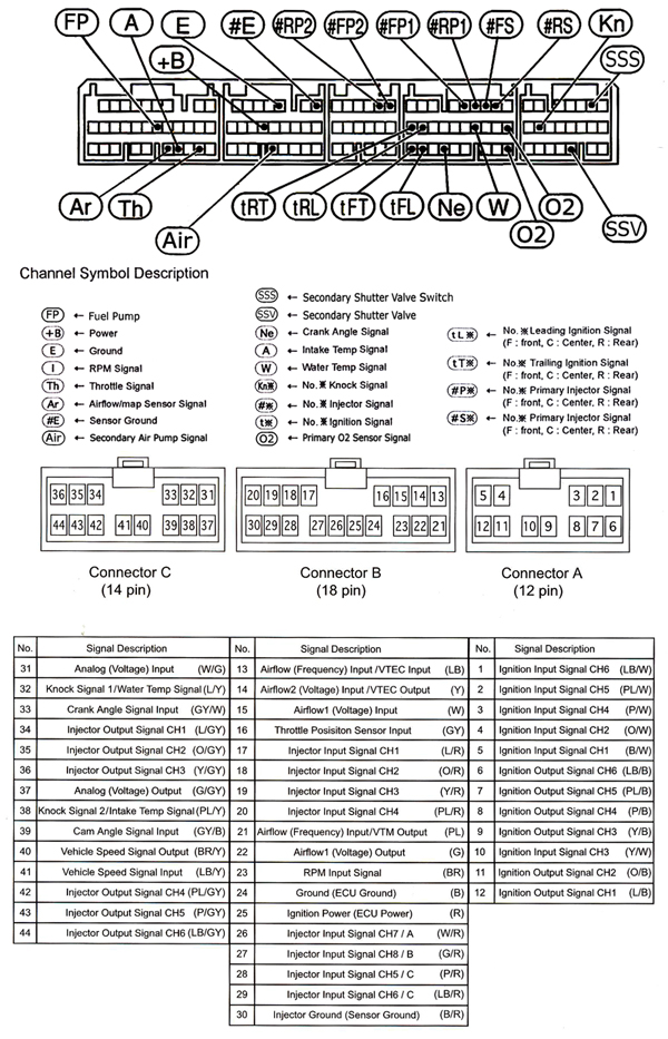
Here is the wiring that I use on my EMU.
See notes for explanations for importance of emphasized connections.
See notes for explanations for importance of emphasized connections.
Jumper Settings
JP1 - Injector Input/Output CH-1 = OPEN (IN/OUT)1
JP2 - Injector Input/Output CH-2 = OPEN (IN/OUT)1
JP3 - Injector Input/Output CH-3 = OPEN (IN/OUT)1
JP4 - Injector Input/Output CH-4 = OPEN (IN/OUT)1
JP5 - Injector Input/Output CH-5 = OPEN (IN/OUT)1
JP6 - Injector Input/Output CH-6 = OPEN (IN/OUT)1
JP7 - Ignition Input = 1-2 (Normal)
JP8 - Ignition Output = 2-3 (12 volt)2
JP9 - Airflow Signal Input/Output = Open (Normal)
JP10 - Airflow Signal Input 2 = 2-3 (VTEC OUT)
JP11 - OPTION 1 = Open (Normal)
JP12 - OPTION 2 = Open (Normal)
JP13 - Knock Signal Input 1/Water Temp Input = 1-2 (Pull Up)
JP14 - Knock Signal Input 2/Water Temp Input = 1-2 (Pull Up)
JP15 - RPM Signal Input = 1-2 (Normal Input)
JP16 - Frequency Input/VTEC Input = 1-2 (VTEC IN)
JP17 - Frequency Output/VTM Output = OPEN (VTM)
JP18 - Injector Input/Output Signal CH1~6 = OPEN (IN/OUT)
JP19 - Injector Signal CH-A = 1-2 (I/J, Sub I/J, NVCS, Relay(-))
JP20 - Injector Signal CH-B = 1-2 (I/J, Sub I/J, NVCS, Relay(-))
Wire Connections:
Ultimate Connector A (12 Pin)
Pin #3 - Ignition Input Signal CH-4 (intercepts) goes to PCM Pin #2Z - Rear Leading Ignition Coil 3
Pin #10 - Ignition Input Signal CH-3 (intercepts) goes to PCM Pin #2AA - Front Leading Ignition Coil 3
Pin #4 - Ignition Input Signal CH-2 (intercepts) goes to PCM Pin #2AC - Rear Trailing Ignition Coil 3
Pin #5 - Ignition Input Signal CH-1 (intercepts) goes to PCM Pin #2AD - Front Trailing Ignition Coil 3
Pin #8 - Ignition Output Signal CH-4 (intercepts) comes from PCM Pin #2Z - Rear Leading Ignition Coil 3
Pin #9 - Ignition Output Signal CH-3 (intercepts) comes from PCM Pin #2AA - Front Leading Ignition Coil 3
Pin #11 - Ignition Output Signal CH-2 (intercepts) comes from PCM Pin #2AC - Rear Trailing Ignition Coil 3
Pin #12 - Ignition Output Signal CH-1 (intercepts) comes from PCM Pin #2AD - Front Trailing Ignition Coil 3
Ultimate Connector B (18 pin)
Pin #15 – Airflow (voltage) Input (intercepts) comes from PCM Pin #5N – MAF
Pin #22 – Airflow (voltage) Output (intercepts) goes to PCM Pin #5N – MAF
Pin #16 - Throttle Pos. Sensor Input (piggybacks) comes from/goes to PCM Pin #5F - Accelerator
Pin #17 – Injector Input Signal CH-1 comes from PCM Pin #2M – Front Primary Injector (intercepted) 4
Pin #18 – Injector Input Signal CH-2 comes from PCM Pin #2J – Rear Primary Injector (intercepted) 4
Pin #19 – Injector Input Signal CH-3 comes from PCM Pin #2G – Front Secondary Injector (intercepted) 4
Pin #20 – Injector Input Signal CH-4 comes from PCM Pin #2D – Rear Secondary Injector (intercepted) 4
Pin #24 – ECU Ground (piggybacks) comes from PCM Pin #4J – PCM EFI Ground
Pin #25 – ECU (Ignition) Power (piggybacks) comes from PCM Pin #4Q – PCM EFI Power
- This wire also connects to the Dongle Red Wire as noted below
- This wire also goes to PCM Pin #1L through a 5k ohm resistor – Secondary Shutter Valve
Pin #26 – Injector Output Signal CH-7/A goes to (piggybacks) PCM Pin #4O – Secondary Air Injection Pump (a diode is inserted on the PCM side) 5- This wire also goes to PCM Pin #1L through a 5k ohm resistor – Secondary Shutter Valve
- This wire also connects to the Dongle Green Wire
Pin #27 – Injector Output Signal CH-8/B goes to (piggybacks) PCM Pin #1L – Secondary Shutter Valve (a diode is inserted on the PCM side) 6Pin #30 – Injector Ground (Sensor) goes to (piggybacks) PCM Pin #4A – Injector Ground
Ultimate Connector C (14 pin)
Pin #32 - Knock Signal 1/Water Temp Signal
Pin #33 – Crank Angle Signal Input (piggybacks) comes from/goes to PCM Pin #2U – Eccentric Shaft Position
Pin #43 – Injector Output Signal CH-5 goes to PCM Pin #3A – Front Primary 2 Injector 7
Pin #44 – Injector Output Signal CH-6 goes to PCM Pin #3D – Rear Primary 2 Injector 7
Pin #34 - Injector Output Signal CH-1 goes to PCM Pin #2M – Front Primary Injector (intercepted) 7
Pin #35 - Injector Output Signal CH-2 goes to PCM Pin #2J – Rear Primary Injector (intercepted) 7
Pin #36 - Injector Output Signal CH-3 goes to PCM Pin #2G – Front Secondary Injector (intercepted) 7
Pin #42 - Injector Output Signal CH-4 goes to PCM Pin #2D – Rear Secondary Injector (intercepted) 7
Ultimate Dongle
Lt.Blue Wire #1 – (piggybacks) comes from/goes to PCM Pin #2B – WBO2S 8
Lt.Blue Wire #2 = (piggybacks) comes from/goes to PCM Pin #2C – WBO2S 8
Green Wire – (piggybacks) comes from/goes to Ultimate Connector B Pin #26 (PCM Pin #4O)
Red Wire – (piggybacks) comes from/goes to PCM Pin #4Q – PCM EFI Power
1 The injection signals should be switched to +/- so that fuel can be trimmed as well as added. This is also a more stable way to wire the injectors, as noted in points 4 and 7.
2 The OP noted that the ignition output is set to 12v. The Ignition on the RX-8 is 5v, so I wasn''t sure why this would be set to 12v.
However, after experimentation, I deduced that the ignition module that is installed on the GReddy board must trim the amplitude of the output signal to mirror the input signal, regardless of this setting.
3 This is the proper order for the ignition wiring as per the installation manual. The OP noted that there was some "crossing" of the ignition lines. I don't have an acceptable theory as to why this would be, but wiring it "correctly" yields proper results.
4 Since we are wiring the injectors as "intercepted" rather than "piggybacked", the wiring for all of the injector lines is changed. Also, I am controlling the Primary 2 injectors as independent sub-injectors rather than "piggybacking" the secondaries as the kit comes wired.
5 Since I am intercepting the injector signals, the NCVS (relay) outputs should be driven by the connector "B" outputs. These are labeled "A" & "B" in the manual.
6 Same as 5
7 Since I am intercepting the injector signals, the injector outputs on connector "C" must be utilized. Note that the sub-injector outputs are now on this connector rather than connector "B" as noted in 5 & 6 above.
8 For some reason, the OP noted that these wires were attached to some other pins. I'm not sure how that could be in his case, but this is how it should be wired and this is how all of the EMU upgrade kit harnesses I have seen are wired. It simply won't work any other way as this is the dongle that spoofs the front O2 sensor.
2 The OP noted that the ignition output is set to 12v. The Ignition on the RX-8 is 5v, so I wasn''t sure why this would be set to 12v.
However, after experimentation, I deduced that the ignition module that is installed on the GReddy board must trim the amplitude of the output signal to mirror the input signal, regardless of this setting.
3 This is the proper order for the ignition wiring as per the installation manual. The OP noted that there was some "crossing" of the ignition lines. I don't have an acceptable theory as to why this would be, but wiring it "correctly" yields proper results.
4 Since we are wiring the injectors as "intercepted" rather than "piggybacked", the wiring for all of the injector lines is changed. Also, I am controlling the Primary 2 injectors as independent sub-injectors rather than "piggybacking" the secondaries as the kit comes wired.
5 Since I am intercepting the injector signals, the NCVS (relay) outputs should be driven by the connector "B" outputs. These are labeled "A" & "B" in the manual.
6 Same as 5
7 Since I am intercepting the injector signals, the injector outputs on connector "C" must be utilized. Note that the sub-injector outputs are now on this connector rather than connector "B" as noted in 5 & 6 above.
8 For some reason, the OP noted that these wires were attached to some other pins. I'm not sure how that could be in his case, but this is how it should be wired and this is how all of the EMU upgrade kit harnesses I have seen are wired. It simply won't work any other way as this is the dongle that spoofs the front O2 sensor.
Last edited by MazdaManiac; Apr 18, 2008 at 05:32 PM. Reason: ©® 2008 MazdaManiac
Thread Starter
Finally Boosted!!!!!!!
Joined: Jan 2006
Posts: 1,035
Likes: 0
From: Central IL
4 Since we are wiring the injectors as "intercepted" rather than "piggybacked", the wiring for all of the injector lines is changed. Also, I am controlling the Primary 2 injectors as independent sub-injectors rather than "piggybacking" the secondaries as the kit comes wired.
8 For some reason, the OP noted that these wires were attached to some other pins. I'm not sure how that could be in his case, but this is how it should be wired and this is how all of the EMU upgrade kit harnesses I have seen are wired. It simply won't work any other way as this is the dongle that spoofs the front O2 sensor.[/INDENT]
Originally Posted by tdiddy
I agree. Are you using the RX-8 specific ignition chip that comes with the upgrade kit? Could the "chip" have something to do with the 12v setting?
I have no idea what it does.
Originally Posted by tdiddy
For a normally aspirated setup, keep the primary 2 injectors as piggyback until you go FI and don't attempt to trim fuel from them. Only trim fuel from the primaries and secondaries.
Originally Posted by tdiddy
Good catch! This was a mistake. My Bad! At least someone is out there checking my work.

Guest
Posts: n/a
ok OCD... maybe I shoulded have worded it air intake temp wire from the MAF sensor, ha ha. Thanks for the reply.
FMI, how did you figure out that it's the 5K? I was able to narrow it down to the two wires mentioned above through process of elimination and didn't want to start cutting wires.
FMI, how did you figure out that it's the 5K? I was able to narrow it down to the two wires mentioned above through process of elimination and didn't want to start cutting wires.
Guest
Posts: n/a
Thanks again Jeff, I got that wired up and found out the jumper 14 needs to be open or it causes the AIT to read 40* lower than actual. So good for relying on the install manual.
Greddy needs to step up and get the water temp to function...they're spending too much time on that V-manage
Greddy needs to step up and get the water temp to function...they're spending too much time on that V-manage
Registered
Joined: Apr 2006
Posts: 84
Likes: 0
From: Mesa, Arizona
What is the exact transistor type you are using? (PNP,NPN, or a FET) and which lead is going where (base, emitter, collector (bipolar transistor) --- or gate,source,drain (FET))? I have a feeling you may be still affecting what the ECU/EMU reads as coolant temp with that transistor in the circuit. If we knew the ECU excitation voltage and the EMU analog/digital converter range/pullup voltage, a better circuit would be had by using an op-amp and a feedback resistor to perfectly scale up/down the voltage without affecting the ECU reading. The input to an op-amp has mega-ohms of input impedance and does not effect the circuit before it in any appreciable way.
I want to understand this too so I can use the E-manage, or a simple comparator circuit to turn on the fans earlier. I have a hard time paying $129 for a particular "cooling fan modification" that a $1 circuit would do just as well.
Well, the PCM is still reading correctly, so the circuit isn't pulling the value either way on the harness.
The problem was that the EMU was reading full low or high (depending on the setup value), probably because its impedance is too low.
I don't even remember which transistor I grabbed out of the bin (I'm famous for that), but the collector goes to the EMU, the emitter goes to ground and the bas goes to the thermistor.
The problem was that the EMU was reading full low or high (depending on the setup value), probably because its impedance is too low.
I don't even remember which transistor I grabbed out of the bin (I'm famous for that), but the collector goes to the EMU, the emitter goes to ground and the bas goes to the thermistor.
Guest
Posts: n/a
I'm pushing about 30 lbs of air through the motor, peak.
My average Pr is about 1.6 - 1.7.
The "problem" is I can't force the leading timing much below 12° - 14° at the torque peak, so at a 10:1 compression and 91 octane (and 115° ambient temperatures!), I'm limited to that kind of Pr.
My average Pr is about 1.6 - 1.7.
The "problem" is I can't force the leading timing much below 12° - 14° at the torque peak, so at a 10:1 compression and 91 octane (and 115° ambient temperatures!), I'm limited to that kind of Pr.
Use the "individual cylinder ignition ADJ MAP", you can pull more timing than you'll ever need.
Also, the individual cylinder ignition ADJ MAP is "static", so that timing differential is fixed to RPM and not load.

