
DIY: Rotary Rasp's Footwell Lights (LEAKED)

Thread Starter
503wtq Boosted Bimmer
iTrader: (2)
Joined: Oct 2004
Posts: 3,038
Likes: 0
From: Los Angeles, California
DIY: Rotary Rasp's Footwell Lights (LEAKED)
I figure it's about time I make this public knowledge. As most of you know, the actual parts to make the footwell lights are pretty cheap. What you were paying for are the instructions that follow....
If you have any questions, please post them in this thread. Other people may have the same questions, or someone else might know the answer to your question. Also, I get a ton of PMs as it is and I haven't owned an rx8 in over 2 years.
If you have any questions, please post them in this thread. Other people may have the same questions, or someone else might know the answer to your question. Also, I get a ton of PMs as it is and I haven't owned an rx8 in over 2 years.
Thread Starter
503wtq Boosted Bimmer
iTrader: (2)
Joined: Oct 2004
Posts: 3,038
Likes: 0
From: Los Angeles, California
Rotary Rasp footwell light installation guide!
Tools Required:
Pliers
Snips
Coat Hanger
Optional Tools:
Electrical Tape
The following guide will help you install your custom LED footwell lights. This guide is provided and intended ONLY for those who purchased Rotary Rasp's footwell LED kit. The follow should take between 15 - 30 minutes depending on your work pace. Read this entire document before starting.
Your kit should include the following.
Driver LED Strip (1)
Passenger LED Strip (1)
Wire Ties (7)
Plastic Mounts (3)
Wire Splice (2)
DSCF0493.jpg?t=1181577783
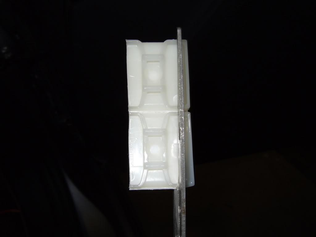
Cut the sides of the plastic mounts. Only do this to two of them.
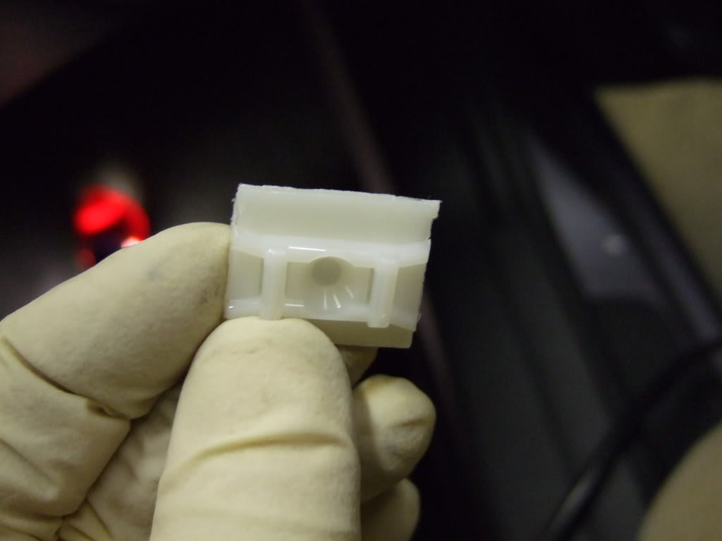
Now you should have two mounts that look like this.
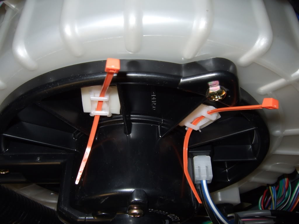
Attach the two trimmed plastic mounts to the AC motor housing. It helps if you slide the two wire ties through the slots before attaching them.
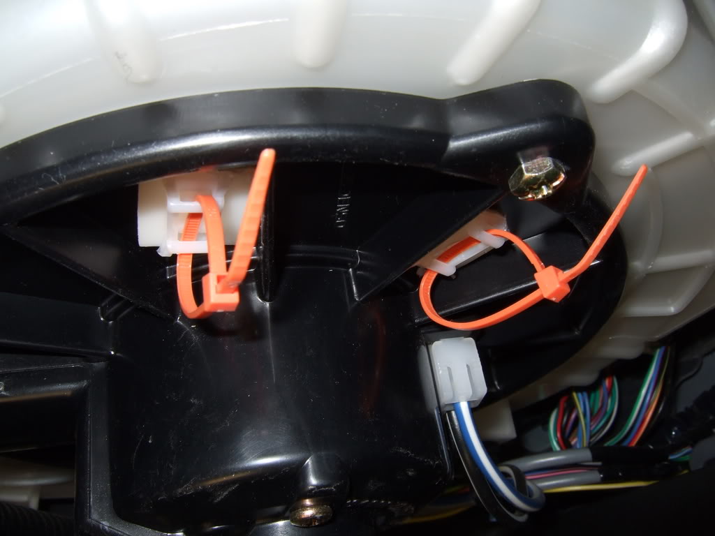
Loop them together like shown. Be sure not to tighten them.
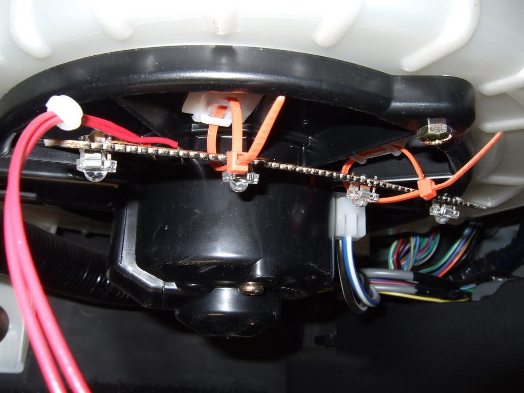
Now slide the passenger LED strip in. The passenger strip has the longer wires.
Now tighten the wires ties. Don't over tighten!
Now slide a coat hanger (or something else) from the drivers slide under the dash. Tape the wires from the passenger LED strip to the other end of the coat hanger.
Now pull the coat hanger back out the drivers side. This will also pull the wires.
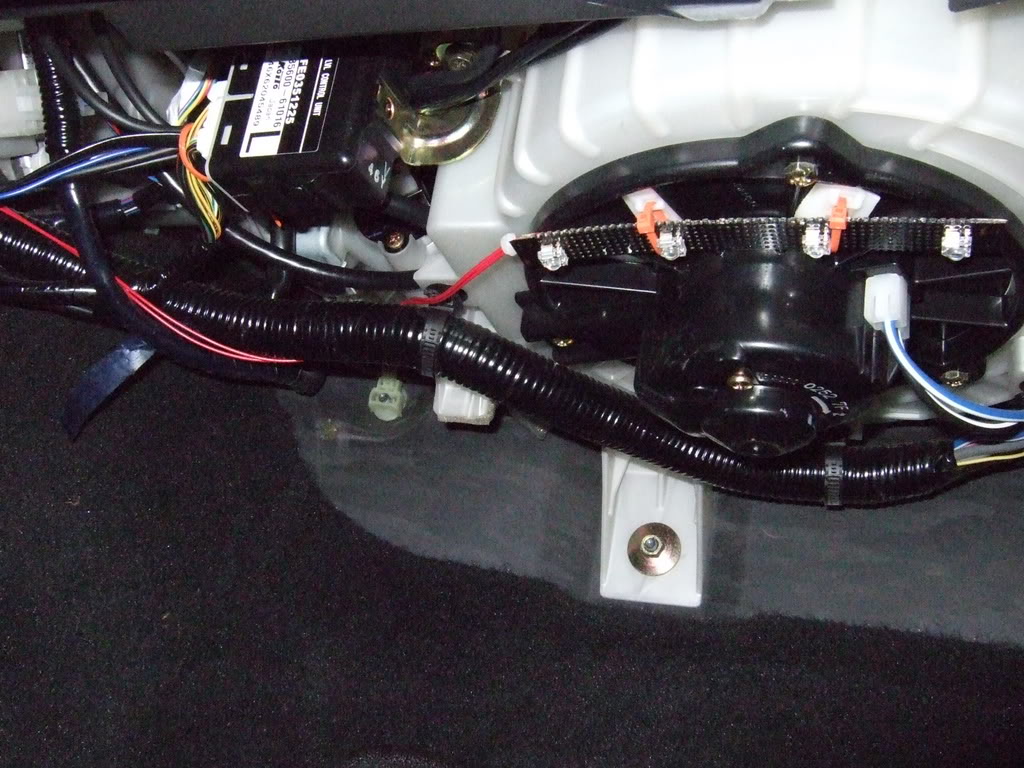
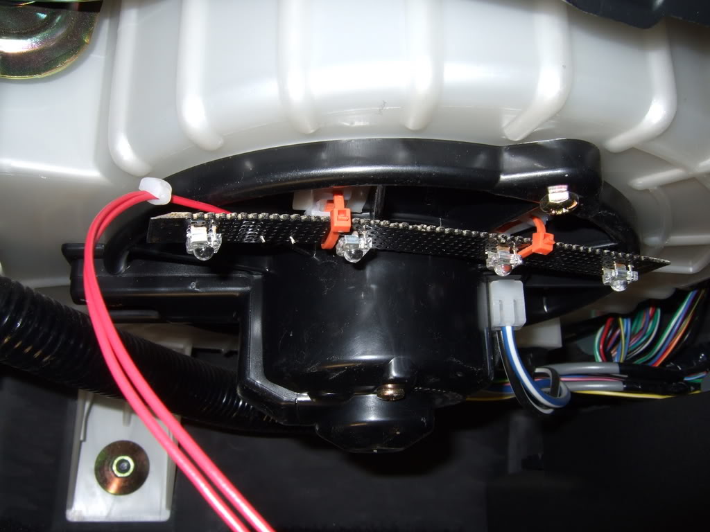
The passenger side is complete and should look like this.
The rest of the work will be done on the drivers side. Now locate the brake pedal and follow it to the top.
Now attach the untrimmed mount to the brake pedal switch. Loop a wire tie through it.
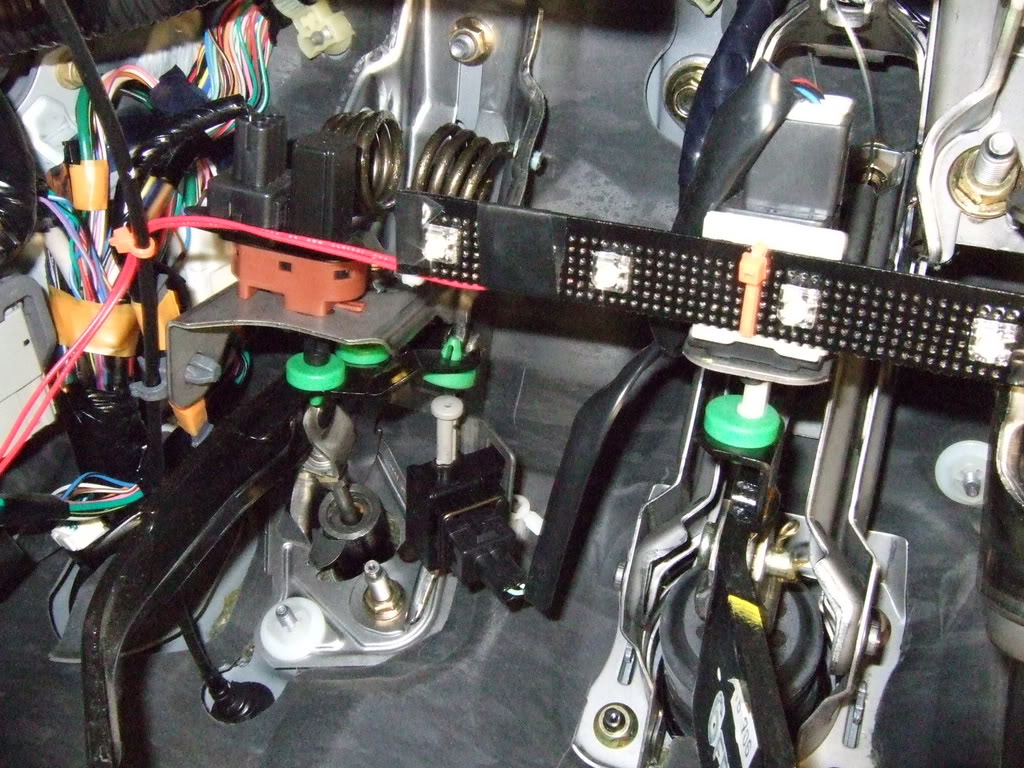
Slide the drivers LED strip in and fasten it like shown.
--- Dome Light Operation ---
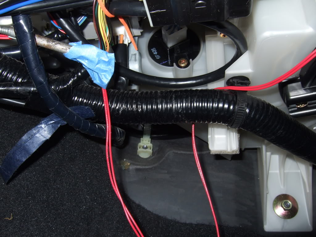
Next find these two wires. You'll need to cut some tape to get to the wires. Scroll down to see a close up shot.
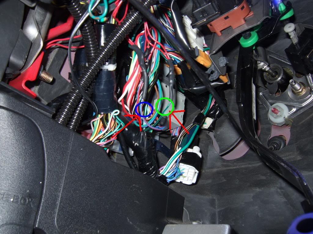
Locate the blue w/ red strip wire. This wire is right above the dead pedal. It may a take a minute to find it among all the other wires. Once you have found the wire, pull it out so you can work on it.
Now locate the green wire from both LED strips. BE SURE YOU HAVE THE CORRECT WIRE. Slide the wire splice onto the blue/red wire. Once that is done, slide the two green wires from the LED strip into it. Notice that one side of the spice has two holes. This is the side the LED wires will be inserted. Once everything is in place, crimp the connector with pliers.
Now in the same area the red/blue wire was found, search for the dark green w/ black strip wire. Once you find that wire, pull it out so you can work on it. Slide a wire splice on the green/black wire. Now take the black wires from the led strips and insert them into the wire spice.
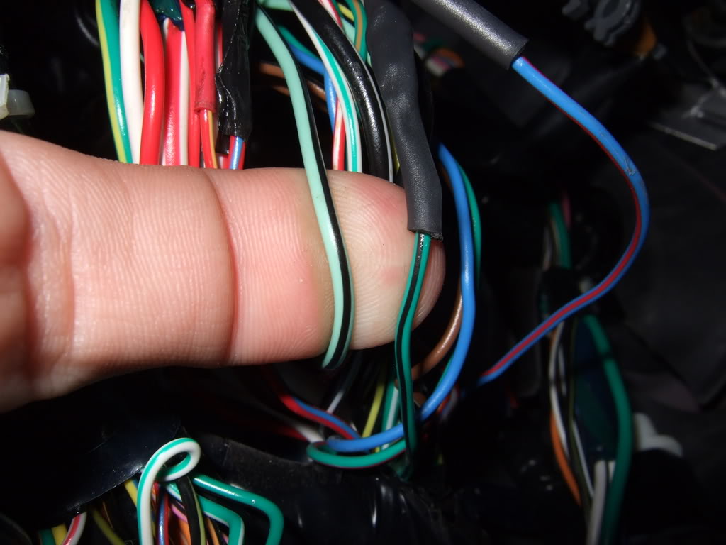
Make sure you tap the dark green wire (right) and NOT the light green.
Once all the wires are pushed in all the way, crimp the connector with the pliers.
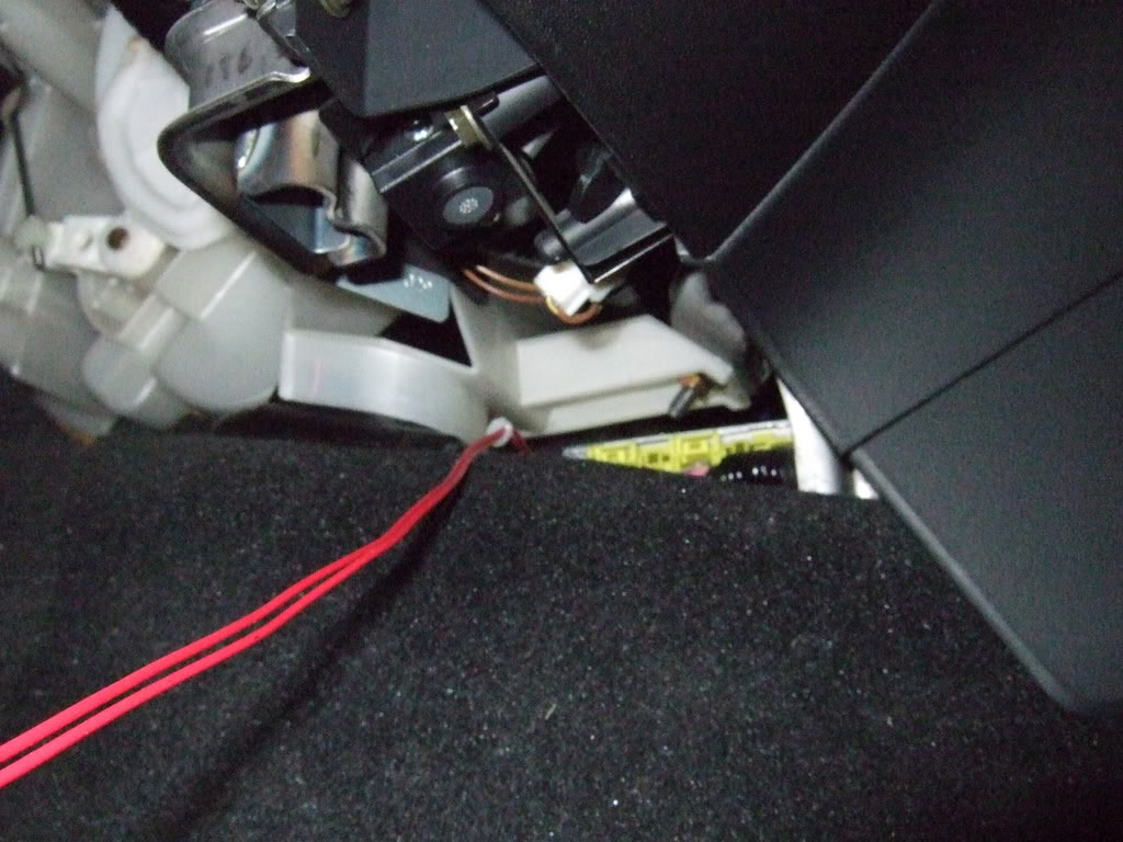
--- Running Light Operation ---
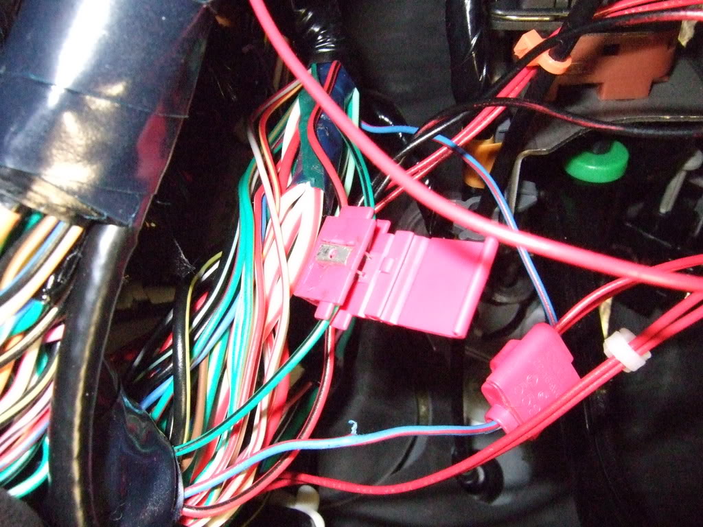
Locate the two wiring harnesses above the OBDII connector.
Now take the green wire from the led strip and splice it into the red/yellow wire. Read above if you need instructions on how to use the provided wire splices.
Lastly, splice the black led wire to the blue/black wire shown above.
Now use the extra wire ties to secure any wires. You can also tape the splices if you want to be extra safe.
That's it!
P.S.
I've attached some pictures taken by DocBeech, please look at them closely.
Tools Required:
Pliers
Snips
Coat Hanger
Optional Tools:
Electrical Tape
The following guide will help you install your custom LED footwell lights. This guide is provided and intended ONLY for those who purchased Rotary Rasp's footwell LED kit. The follow should take between 15 - 30 minutes depending on your work pace. Read this entire document before starting.
Your kit should include the following.
Driver LED Strip (1)
Passenger LED Strip (1)
Wire Ties (7)
Plastic Mounts (3)
Wire Splice (2)
DSCF0493.jpg?t=1181577783
Cut the sides of the plastic mounts. Only do this to two of them.
Now you should have two mounts that look like this.
Attach the two trimmed plastic mounts to the AC motor housing. It helps if you slide the two wire ties through the slots before attaching them.
Loop them together like shown. Be sure not to tighten them.
Now slide the passenger LED strip in. The passenger strip has the longer wires.
Now tighten the wires ties. Don't over tighten!
Now slide a coat hanger (or something else) from the drivers slide under the dash. Tape the wires from the passenger LED strip to the other end of the coat hanger.
Now pull the coat hanger back out the drivers side. This will also pull the wires.
The passenger side is complete and should look like this.
The rest of the work will be done on the drivers side. Now locate the brake pedal and follow it to the top.
Now attach the untrimmed mount to the brake pedal switch. Loop a wire tie through it.
Slide the drivers LED strip in and fasten it like shown.
--- Dome Light Operation ---
Next find these two wires. You'll need to cut some tape to get to the wires. Scroll down to see a close up shot.
Locate the blue w/ red strip wire. This wire is right above the dead pedal. It may a take a minute to find it among all the other wires. Once you have found the wire, pull it out so you can work on it.
Now locate the green wire from both LED strips. BE SURE YOU HAVE THE CORRECT WIRE. Slide the wire splice onto the blue/red wire. Once that is done, slide the two green wires from the LED strip into it. Notice that one side of the spice has two holes. This is the side the LED wires will be inserted. Once everything is in place, crimp the connector with pliers.
Now in the same area the red/blue wire was found, search for the dark green w/ black strip wire. Once you find that wire, pull it out so you can work on it. Slide a wire splice on the green/black wire. Now take the black wires from the led strips and insert them into the wire spice.
Make sure you tap the dark green wire (right) and NOT the light green.
Once all the wires are pushed in all the way, crimp the connector with the pliers.
--- Running Light Operation ---
Locate the two wiring harnesses above the OBDII connector.
Now take the green wire from the led strip and splice it into the red/yellow wire. Read above if you need instructions on how to use the provided wire splices.
Lastly, splice the black led wire to the blue/black wire shown above.
Now use the extra wire ties to secure any wires. You can also tape the splices if you want to be extra safe.
That's it!
P.S.
I've attached some pictures taken by DocBeech, please look at them closely.
Last edited by Rotary Rasp; Nov 30, 2010 at 06:28 PM.


Thread Starter
503wtq Boosted Bimmer
iTrader: (2)
Joined: Oct 2004
Posts: 3,038
Likes: 0
From: Los Angeles, California


Registered
Joined: Sep 2009
Posts: 55
Likes: 0
From: San Jose, CA
Hey Rasp, having trouble finding the dark green with black & blue with red due to the fact that there are multiples.
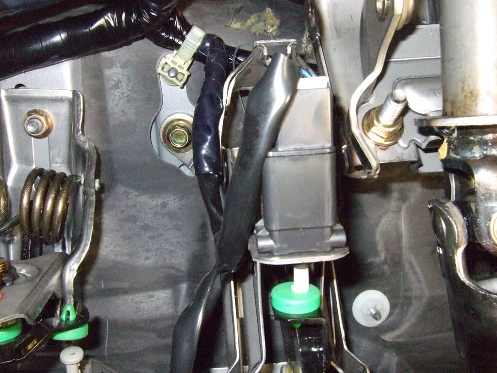
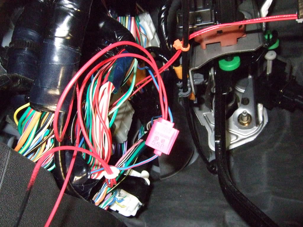
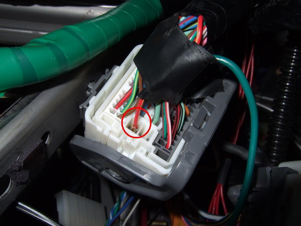
I know for sure the first ones I found (closest to the steering wheel & above the wires for running headlight) were wrong. I found another set of the same wires above the dead pedal. The question is... the two wires I found are connected to a big light grey box (see attached). Are these the right one? Having trouble finding the right ones just by looking @ the picture.
Thanks!!
ok to answer both of your questions. I did notice this do it yourself isn't exactly accurate. so the wiring harness you are looking for is the one comming from the door. Find the connection and bundle that runs into the door, it sits a little high. If you have to cut any electrical tape you did it wrong. The wires you are looking for are already exposed, I had to do no cutting.
secondly as far as the light strips go, I have been using this strip from www.superbrightleds.com
WFLS-x30-BK Flexible Light Strip - Black Circuit
next goto your local hardware store, or someone that supplies picture hanging tape. Its like double sided super tape because the 3m adhesive sucks on our car. using that hanging tape position the light strip in front of your pedals or it won't shine on them correctly.
Registered
Joined: Sep 2009
Posts: 55
Likes: 0
From: San Jose, CA
Oh man..i definitely got it wrong then? I've cut through some tape both times I'll hit it again first thing tomorrow morning!!
I'll hit it again first thing tomorrow morning!!ok to answer both of your questions. I did notice this do it yourself isn't exactly accurate. so the wiring harness you are looking for is the one comming from the door. Find the connection and bundle that runs into the door, it sits a little high. If you have to cut any electrical tape you did it wrong. The wires you are looking for are already exposed, I had to do no cutting.
secondly as far as the light strips go, I have been using this strip from www.superbrightleds.com
WFLS-x30-BK Flexible Light Strip - Black Circuit
next goto your local hardware store, or someone that supplies picture hanging tape. Its like double sided super tape because the 3m adhesive sucks on our car. using that hanging tape position the light strip in front of your pedals or it won't shine on them correctly.
Registered
Joined: Sep 2009
Posts: 55
Likes: 0
From: San Jose, CA
Just an update:
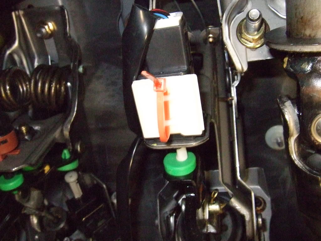
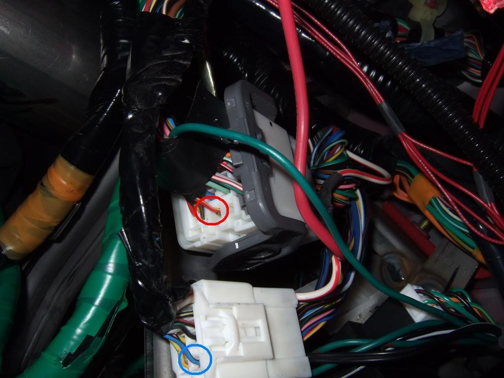
the running lights are now up and running! Hoooraaay! Just gotta do some last touches on it. Attached is a picture of where I thought the green/black & blue/red would be. Unfortunately, the light is constantly on and only flickers when I play with my keyless entry buttons. Could've sworn I had the right bunch this time :|
http://www.youtube.com/watch?v=Lbpd1r47Cdg
Last edited by dohon; Oct 9, 2010 at 10:04 PM.
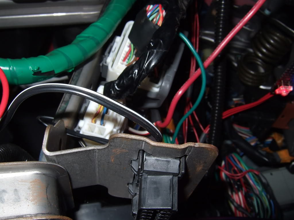
If you look in the photos, I have marked them. The harness you are looking for comes out of the door than curves. You do not have to cut any tape to get to the wires. The little c shaped wiring harness is also a no no. The harness that mazda put 100 yards of tape around is a no go as well.
Just making sure these directions are for two applications, One for the dome lights (the door lights) and the running lights? Don't want to make a mistake to splicing the footwells into both wires.
Registered
Joined: Sep 2009
Posts: 55
Likes: 0
From: San Jose, CA

yes the application I posted photos on is connecting them to the dome light circuit. Actually though its not the dome light circuit its the courtesy light circuit. It makes them come on when you push the unlock button or open the doors. It does not come on with the dome light.
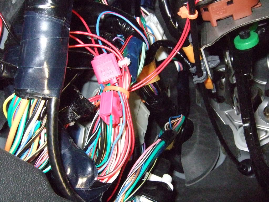
Basically what you need to do is feel for the wiring harness that comes in and out of the door. Follow that to the area where the wires are exposed. There will be two other harnesses. One very short in a C shape in the back, and the other has a serious amount of very heavy electrical tape on it. Avoid those two sets and your will be fine. I also suggest you sodder into the lines since the wires are so small and fragile.
Basically what you need to do is feel for the wiring harness that comes in and out of the door. Follow that to the area where the wires are exposed. There will be two other harnesses. One very short in a C shape in the back, and the other has a serious amount of very heavy electrical tape on it. Avoid those two sets and your will be fine. I also suggest you sodder into the lines since the wires are so small and fragile.


Well I went and replaced the map, courtesy, and rear overhead lights with red LEDs. the rear overhead wont work so I took the whole assembly out and it looks like it was somewhat burnt where the bulb sits any idea where i can buy a new assembly. Also I did the footwells today and I'm pretty sure i tapped into the wrong wires lol cuz it wont shut off at all they blink when left turn signal is on and dsc off blinks
Last edited by zildijianxiv; Nov 24, 2010 at 09:01 PM.


Thread
Thread Starter
Forum
Replies
Last Post
Modified Dave
Canada For Sale/Wanted
4
Mar 5, 2016 04:36 PM
9krpmrx8
Series I Trouble Shooting
23
Nov 5, 2015 11:45 PM
akagc
RX-8's For Sale/Wanted
7
Aug 11, 2015 07:07 PM