
Mazda recently published patent: FR rear suspension


Thread Starter
Wiseguy
Joined: Aug 2008
Posts: 1,084
Likes: 37
From: Italy
Mazda recently published patent: FR rear suspension
searchin' into patentstorm.us site i've found this patent (you need logging for viewing PDF)
http://www.patentstorm.us/patents/pd...d/7703565.html
in my opinon is not the same rear axis that we found into mx-5

Don't seems to me the rx-8's axis too, i'm wrong or what?
Any toughs? new Mazda sportcar axis?
http://www.patentstorm.us/patents/pd...d/7703565.html
in my opinon is not the same rear axis that we found into mx-5
Don't seems to me the rx-8's axis too, i'm wrong or what?
Any toughs?
new Mazda sportcar axis?

Momentum Keeps Me Going
Joined: Sep 2002
Posts: 5,036
Likes: 5
From: Colorado
Nice find..don't really know what a MX-5 chassis looks like, but this is certainly a sports car chassis...no doubt about it. And lots of pulleys up front there...ummm.
Maybe it's this one...or something like it actually ready for production? Or..or..?
http://www.carbodydesign.com/archive...light-version/
The engine shows a striking resemblance to a standard MX-5 NA engine it seems.
Maybe it's this one...or something like it actually ready for production? Or..or..?
http://www.carbodydesign.com/archive...light-version/
The engine shows a striking resemblance to a standard MX-5 NA engine it seems.
Last edited by Spin9k; Apr 29, 2010 at 08:21 AM. Reason: corrected resembance to..

Thread Starter
Wiseguy
Joined: Aug 2008
Posts: 1,084
Likes: 37
From: Italy
my english skills are not so good to understand what EXACTLY means a so technical article, sorry...i'm asking to you, guys..
P.S. the picture posted is obiuovsly reffered to current mx-5 to compare quickly the two rear axis, and the differences.
need logginig to see from patentstorm...it's easy and free BTW....
EDIT: try this one
http://www.freepatentsonline.com/7703565.html
P.S. the picture posted is obiuovsly reffered to current mx-5 to compare quickly the two rear axis, and the differences.
need logginig to see from patentstorm...it's easy and free BTW....
EDIT: try this one
http://www.freepatentsonline.com/7703565.html
Last edited by MattMPS; Apr 29, 2010 at 08:36 AM.

Administrator
Joined: Jul 2002
Posts: 21,958
Likes: 115
From: portland oregon
This is actually about adding electric motors to the rear wheels in such a way that they will not interfere with the suspension.
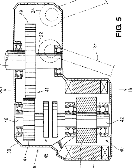
Figures 5 and 6 are the important ones as well as the text after. you can see in figure 5 how they offset the drives in that L shaped box that connect to the diff in .
There's more text Ill add in amoment.
Figures 5 and 6 are the important ones as well as the text after. you can see in figure 5 how they offset the drives in that L shaped box that connect to the diff in .
There's more text Ill add in amoment.
Thread Starter
Wiseguy
Joined: Aug 2008
Posts: 1,084
Likes: 37
From: Italy
mx-5 maybe....?
Note the brake calipers OUTSIDE the wheelbase (in NC/RX-8 are INSIDE WB)
Administrator
Joined: Jul 2002
Posts: 21,958
Likes: 115
From: portland oregon
So here is the relevant text that talks abotu electric drive motros and situatiing them is an offset manner so as to esure the suspension can be of appropriate lengths with inteference fromt eh palcement of the motors
The present invention relates to a disposition structure of a drive device for a vehicle, such as an electric automobile or a hybrid vehicle, which comprises a drive motor to drive a rear wheel that is disposed in a wheel.
Recently, a technology in which a drive motor to drive a vehicle wheel is disposed in a wheel (a so-called in-wheel motor) in order to simplify a drive-force transmitting system from a power resource to the vehicle wheel has been developed (see Japanese Patent Laid-Open Publication Nos. 2006-248273 and 2006-248417).
A right wheel and a left wheel of the vehicle can be controlled independently by the drive motor pro-vided for each wheel. Accordingly, this vehicle has really effective advantages in its practical operation.
Meanwhile, in a case where the above-described drive motors are applied to rear wheels of the vehicle, there is a problem in that a relatively large-sized drive motors would interfere with suspension links that are provided so as to extend substantially in a vehicle width direction with an appropriate length for properly controlling positions of the rear wheels (such as a camber angle).
SUMMARY OF THE INVENTION
An object of the present invention is to provide a disposition structure of a drive device for a vehicle that can provide both the drive motors and the suspension links without any improper interference therebetween, ensuring proper controlling of the wheel position.
According to the present invention, there is provided a disposition structure of a drive device for a ve-hicle, comprising a drive motor operative to drive a rear wheel, the drive motor being disposed in a wheel, a plurality of suspension links, one end of each of which is coupled to the wheel and the other end of each of which is coupled to a vehicle body, the suspension links being disposed so as to extend substantially in a vehicle width direction, and a drive-force transmitting mechanism operative to couple the drive motor to the wheel so as to transmit a drive force, wherein the drive motor is disposed so as to be offset from a center of the wheel on a side that is away from a disposition location of the suspension links.
According to the above-described structure, since the drive motor is disposed so as to be offset from the center of the wheel on the side that is away from the disposition location of the suspension links, both the drive motor and the suspension links with the appropriate length can be properly provided without any improper interference therebetween, ensuring the proper controlling of the wheel position. Further, there can be provided a large-sized drive motor that ensures a sufficient output torque. Also, a layout flexibility of the plural suspension links and the drive motor is improved, so a vehicle compartment or a baggage compartment can be properly enlarged.
According to an embodiment of the present invention, the drive motor is disposed so as to be offset from the center of the wheel on a vehicle forward side, and the suspension links are disposed behind the drive motor. Thereby, the drive motor as a relatively heavy-weight object is disposed at a location that is closer to the center of the vehicle, so a yawing moment of inertia can be reduced. Also, the ap-propriate length of the suspension links can be ensured.
According to another embodiment of the present invention, the drive motor is disposed so as to overlap at least part of the suspension link in an elevation view. Thereby, the suspension link (see an upper link) can be disposed in a dead space that is produced by the drive motor's offset disposition, ensuring disposition of the large-sized drive motor, so the layout flexibility of the suspension links can be improved.
According to another embodiment of the present invention, the drive motor is disposed so as to overlap at least part of the suspension link in a plan view. Thereby, disposition of the large-sized drive motor and proper disposition of the suspension link (see a lower link) can be made compatible.
According to another embodiment of the present invention, the suspension links comprise an upper link that is disposed above the center of the wheel, and the upper link is disposed behind the drive motor. Thereby, disposition of the large-sized drive motor and disposition of the upper link with an appropriate length can be made compatible.
According to another embodiment of the present invention, the suspension links comprise a lower link that is disposed below the center of the wheel, and the lower link is disposed behind the drive motor. Thereby, disposition of the large-sized drive motor and disposition of the lower link with an appropriate length can be made compatible.
According to another embodiment of the present invention, the upper and lower links respectively comprise a pair of links, and the upper and lower links are respectively disposed such that a longitudinal distance between one ends thereof coupled to the wheel is smaller than that between the other ends thereof coupled to the vehicle body. Thereby, each disposition angle of the pair of links can be properly set, the appropriate length of the upper and lower links can be ensured, and the large-sized drive motor can be disposed.
According to another embodiment of the present invention, there is provided a toe-control link that extends substantially in the vehicle width direction, one end of which is coupled to the wheel and the other end of which is coupled to the vehicle body, and the one end of the toe-control link that is coupled to the wheel is disposed so as to be offset from the center of the wheel on a side that is away from a disposition location of the drive motor. Thereby, disposition of the large-sized drive motor and disposition of the toe-control link can be made compatible, the sufficient output torque can be ensured by the large-sized drive motor, and proper controlling of the wheel position, especially a toe angle of the wheel, can be achieved by the above-described disposition of the toe-control link. Also, a layout flexibility of the toe-control link and the drive motor is improved, so the vehicle compartment or the baggage compartment can be properly enlarged.
According to another embodiment of the present invention, the toe-control link is disposed below the drive motor. Thereby, both the drive motor and the toe-control link can be more properly disposed.
According to another embodiment of the present invention, in the wheel is provided a brake disc that rotates with the rear wheel and a brake caliper that controls the brake disc, and the brake caliper is disposed so as to be offset from the center of the wheel on a side that is away from a disposition location of the drive motor. Thereby, respective disposition of the large-sized drive motor, a large-sized brake caliper and the suspension links can be made compatible. Also, the sufficient output torque can be ensured by the large-sized drive motor, and a proper braking force can be ensured by the large-sized brake caliper.
According to another embodiment of the present invention, the brake caliper is disposed behind the drive motor. Thereby, the drive motor that has its heavier weight than the brake caliper is disposed at a location that is closer to the center of the vehicle, so the yawing moment of inertia can be properly reduced.
Other features, aspects, and advantages of the present invention will become apparent from the following description which refers to the accompanying drawings.
Administrator
Joined: Jul 2002
Posts: 21,958
Likes: 115
From: portland oregon
Thread Starter
Wiseguy
Joined: Aug 2008
Posts: 1,084
Likes: 37
From: Italy

Administrator
Joined: Jul 2002
Posts: 21,958
Likes: 115
From: portland oregon
well they certainly arent hiding  whether it means production soon ... who knows?
well I suppose those fellows whose name is on the patent. You should call up the front desk at Mazda and ask to speak with one of them
"Hello I'd like to speak to Kenji please.....
No, Kenji.... what do you mean which Kenji? Kenji Asada.
Eh? Oh hi yes tell him its his brother , Mark."
For some reason I hear that in an Eric Idle voice^
whether it means production soon ... who knows?well I suppose those fellows whose name is on the patent. You should call up the front desk at Mazda and ask to speak with one of them
"Hello I'd like to speak to Kenji please.....
No, Kenji.... what do you mean which Kenji? Kenji Asada.
Eh? Oh hi yes tell him its his brother , Mark."
For some reason I hear that in an Eric Idle voice^


Matt,
You're discovery of this patent is impressive. It is demonstrative of the excellent investigative research members of this forum are continuously doing or people with too much time on their hands.
Paul.
You're discovery of this patent is impressive. It is demonstrative of the excellent investigative research members of this forum are continuously doing or people with too much time on their hands
.Paul.
Super Moderator
Joined: Apr 2005
Posts: 10,880
Likes: 340
From: Australia
Administrator
Joined: Jul 2002
Posts: 21,958
Likes: 115
From: portland oregon
wtf?!?!?!?
where's the "thanks, charlie" for sending it in to them?
they've always done it before when i send tips into them. now they act like they are the ones that found it when I was the one trying to steal matt's thunder!
where's the "thanks, charlie" for sending it in to them?
they've always done it before when i send tips into them. now they act like they are the ones that found it when I was the one trying to steal matt's thunder!
Administrator
Joined: Jul 2002
Posts: 21,958
Likes: 115
From: portland oregon
and what dont those commentors understand? this is also acting as a torque multiplier AND Mazda can have the suspension they WANT instead on the suspension ALLOWED. Its for making sure the MX-5 and RX-59y7598450 still get to be fun to drive even when they have to get into electrics and hybrids.
 .
.Paul


Thread
Thread Starter
Forum
Replies
Last Post
WingleBeast
Series I Wheels, Tires, Brakes & Suspension
22
May 23, 2016 09:22 PM
akagc
RX-8's For Sale/Wanted
7
Aug 11, 2015 07:07 PM
N0P1st0ns
Series I Aftermarket Performance Modifications
4
Jul 30, 2015 09:45 AM