View Full Version : OEM Navigation Hood Retrofit for Carputer Application
RA-Eight 03-14-2008, 11:51 AM Goal: To install the OEM Navigation hood into a car that did not come with the Nav option, and maintain the motorized “Open” and “Tilt” flip-up functions.
Background: A lot of us are beginning to get into carputer builds for our cars. Most of us want to maintain that OEM look and feel and decided one of the better options is to house our carputer screen in the OEM navigation hood. For owners whose car came with the factory nav option, it’s almost as simple as replacing the stock LCD display with a higher resolution, touch screen display, with no issues retaining the Open/Tilt function. However, for those cars that did not come with the nav option, it becomes a little tougher. Up until this point, people either leave buttons non-functional and manually flip up the screens, one person managed to build a circuit board to control the functions (see following link), or give up all together.
http://www.rx8club.com/showthread.php?t=87146
So my first disclaimer is that I’m not a car electronic guru. I’m hoping that between all the engineers, and experts on this forum, we can find a solution to probably a simple problem. Maybe as simple as tap here for POWER, here for ACC, and here for GROUND.
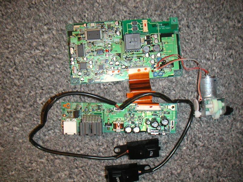
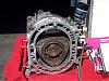
Here is a picture of the on-board PCB, which is located on the back of the OEM nav LCD. I believe these PCBs control the motor that opens/tilt the hood, as well as feeding the video signals to the LCD:
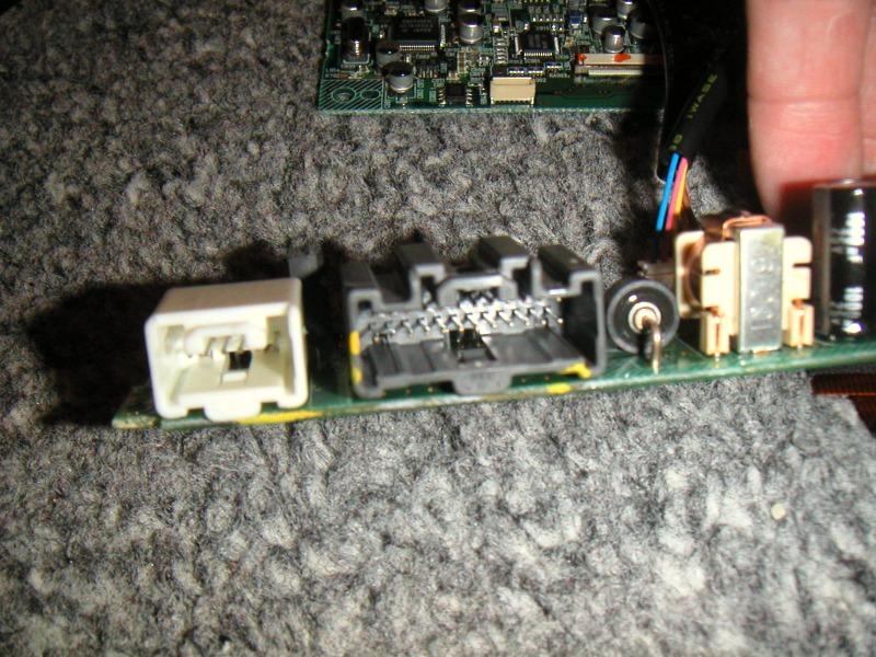
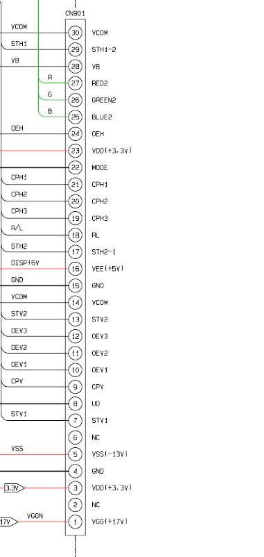
http://www.rx8club.com/attachment.php?attachmentid=74364&d=1144689476
Nav wire harness (24 pin – 2 rows; 6 pin – 1 row):
http://www.rx8club.com/attachment.php?attachmentid=74365&d=1144689476
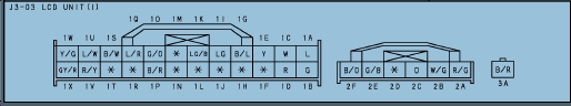
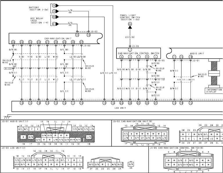
Here are the diagrams from the electrical manual:
http://www.rx8club.com/attachment.php?attachmentid=117084&stc=1&d=1205509772
http://www.rx8club.com/attachment.php?attachmentid=117083&stc=1&d=1205509772
RA-Eight 03-14-2008, 11:52 AM To the electrical engineers, can you point out on the 24 pin harness, which pin is for POWER, ACC, and GROUND? Is it as simple as feeding the PCB power?
frollo 03-14-2008, 12:11 PM holy crap thank you for posting these! i am actually getting ready to start my install here soon as soon as g3treddy ships me my hood :) i realize it was posted before however i hadn't come across these yet, i too am interested in the answer
kimota 03-14-2008, 03:43 PM You may want to PM MSTYLES he's retrofitted the OEM Nav hood but hasn't been on in a few months :(
P.S
His eight is absolutely outrageous
frollo 03-18-2008, 10:46 AM i might have to send him a pm or two myself :)
RA-Eight 03-18-2008, 12:22 PM I have myself. ;) fingers crossed!
frollo 03-18-2008, 12:29 PM let me know what you come up with i will be following in your footsteps :) also if you want to take pictures on where you hooked up to power and everything you would be forever leet in my mind :)
RA-Eight 03-18-2008, 12:48 PM LOL - I was hoping you'd resolve it first!
frollo 03-27-2008, 04:21 PM can't be the first havn't gotten my hood yet! :) you get it figgured out yet? i am thinking it is going to be a nightmare to get this thing all hooked up and working
RA-Eight 03-27-2008, 09:30 PM Not yet. Just got my Carnetix P2140 and I've been playing with that. What's taking your hood so long?
frollo 03-28-2008, 12:16 AM my own excitement i believe i thought it was sent two weeks ago it was sent last friday. stupid anxiety ;) so excited to get this thing going only to run into a brick wall w/ the hood lol. i also need to get my hd radio cable in. sinec he just got stock a few days ago i'm going to be a bit frustrated if i get it before the hood :D usps better not be slow. i wanted to get a full weekend of attempts in w/ the hood this weekend, unless it shows up tomorrowit doesn't look like that will happen.
frollo 03-29-2008, 09:59 PM got my hood friday been dicking around with it all weekend so far... havn't messed w/ electrical yet however it looks like it is going to suck. i have been dremeling out the hood to fit the screen atm it is quite a mess lets hope it works out alright
frollo 03-30-2008, 10:47 PM hey i found this http://www.rx8club.com/showthread.php?t=78367&page=4 do you know if this is the right one?
RA-Eight 03-31-2008, 12:16 PM I don't know how this rail diagram correlates to the 12x2 pin harness.
http://www.rx8club.com/attachment.php?attachmentid=62351&stc=1
frollo 03-31-2008, 12:47 PM i was thinking 12x2 = 24 + the other 6 cable but who knows
RA-Eight 03-31-2008, 01:06 PM Makes perfect sense! Shows you how much I can read an electrical diagram!
Now where does the 24 end and 6 begin? Or vise versa?
frollo 03-31-2008, 01:32 PM by the wires i was thinking 25-30 would be the 6 separate wires however don't quote me on that i was asking if anybody knew if it was the correct diagram
moete87 04-01-2008, 11:17 PM I ran into this same problem when I had my hood and just gave up on it. It became too much of a headache to get everything figured out and the hood and screen was just sitting around waiting to be installed and I was getting frustrated..so I sold both and got the MS front bumper instead! :)
Best of luck to you guys! Its a total bitch!!
frollo 04-03-2008, 12:11 PM got pretty much everything installed atm and i am just going to make a circuit to drive the motor as mote is correct there is about no way to figgure this out in a decent amount of time
RA-Eight 04-28-2008, 09:14 PM I've tested every pin with a multimeter, and with my very limited knowledge and after some sparks flying, doesn't look like I can find and isolate the correct signal to power the unit and control the hood.
I am in the process of building the circuit from rprzybyl in this thread (http://www.rx8club.com/showthread.php?t=87146&page=2) . I'm at a point where I need to figure out which pin on the relay hooks up to the wires coming out of the servo/motor.
RA-Eight 04-28-2008, 09:16 PM Pics of the carputer:
http://i32.photobucket.com/albums/d27/rax8/carputer/c7e9988e.jpg
Nav hood and Xenarc monitor that will be replacing the OEM screen in the hood:
http://i32.photobucket.com/albums/d27/rax8/carputer/img022.jpg
Xenarc monitor with StreetDeck running:
http://i32.photobucket.com/albums/d27/rax8/carputer/img020.jpg
MazdaJeff 05-04-2008, 12:04 PM Hey RA 8, did you buy the motorized housing separately?
I'm considering doing the whole car PC thing as well......
frollo 05-05-2008, 06:32 PM i also did the same ra can you post the pix of your circuit both top and bottom when you finish? i have had problems w/ my relay. aka power goes in switch works no power comes out doesn't matter if it is switched or not. even wired according to the back of the box as best i can tell :) i didn't find one that is the exact same as the wireing doc though and got one from radio shack w/ the same power numbers
MazdaJeff 05-06-2008, 02:41 PM Well, I just found a used motorized nav housing. Should have it next week. Hopefully we can come up with a solution......
alz0rz 05-06-2008, 03:04 PM is it really so hard to get the motor powered so you can open and close it? i would have thought it'd be easy as that.. get rid of the pcb and feed the motor current directly.. bahhh!
frollo 05-06-2008, 11:11 PM and then power the lights in the buttons how? if you hook the two different buttons up to the same motor how would you prevent flow going back through the buttons and all the problems that lie there? and what about having the tilt turn the motor slower? all things the circuit does assuming you can get it working correctly
RA-Eight 05-07-2008, 10:11 AM So my attempt at building the circuit failed miserably. It may have to do with the relay I bought. The Radio Shack guys recommended a DPDT relay. I believe my issue is the hookup between the relay and the servo/motor. I've tried multiple combinations. I did manage to get the "Tilt" button to light up, and it did make the motor run, very slowly. The "Open" button light did not light up. It did trigger something in the relay, but the motor did not go.
MazdaJeff 05-22-2008, 10:03 PM Finally got my nav hood. Started playing with it. We got power to it, but that is about it. If we manually open the screen and turn the power on it shuts. Now we have to figure out which circuits to close to make it operation.
I will keep you guys posted.
ApeWare 05-23-2008, 09:15 PM RA-Eight,
your pin-out drawing is incomplete. where is the rest of it? The page you have shows the ground but it goes off the page so it is not possible to give you the location of the ground - I am assuming it is the black wire on the harness, you will need to verify.
Second, this schematic does not include the motor (or controller) for the LCD unit. So not going to be able to trace it out.
See attachment for my best (educated) guess, based on the info provided.
Maybe a place for you to start with a VM anyway. If you get the rest of the diagram (and the one for the motor controller, I may be able to help further.
Good luck. Please take pics along the way. I may follow in your footsteps if I get the courage to rip my baby apart.
Chainu127 07-10-2008, 08:14 PM Hi all,
I'm working on a solution to this as I recently purchased an RX-8 with the intention of putting a car computer in it. I did not want factory nav because the console buttons and oem dvd-rom would be useless after replacing the lcd. I was fortunate enough to find a used hood + stock screen for $150 (few scratches, does anyone know how to get small scratches out of plastic?). Anyway, seeing as I do not have the nav harness and that I work at Microchip, I decided to use a microcontroller to replace the circuit board of the oem screen. I have got preliminary motor control working but I want to retain some features like dimming lights and last position memory. Does anyone have any knowledge of how the dimming works with the open/tilt buttons? The only information I found was for the stereo:
'PULSED DIMMER TNS+' (pin e) is somewhat of a misnomeras it is not pulsed at all. It is a line that switches to +12v when the light switch is either in PARK or HEADLIGHT position. When lights are switched off it is at 0V. It provides a +12v signal to indicate that some exterior lighting is on.
'INVERTED DIMMING' (pin g) is 0V when the panel dimmer is in the detent position. When it is switched out of detent and advanced a bit, a narrow 12v pulse starts at a period of approximately 5mSec (minimum dimming), and as the dimmer is advanced, the pulse gets wider until it is at 12v for 4.2mSec and at 0v for 0.8mSec out of the 5mSec for maximum dimming. This signal provides a varying pulsewidth Ov signal to the negative side of the panel lights.
In the diagram below I find Illumination + and Illumination - connections, but in my testing I can't make the buttons light through those. Does anyone know how this works or have any more information? I don't have the factory nav harness so I can't test the wires myself.
PS: since it hasn't been answered, pin 1Q goes to battery, 1O goes to ACC, and 1P goes to ground in the diagram on the first post (connection J3-03, bottom left corner, the picture is as if you were looking at the back of the unit) nothing needs to go on the white connector. This will give you motor control and position memory, but no button lights.
RA-Eight 07-11-2008, 09:10 AM That is awesome, Chainu127. Hope you can crack this.
Update on my progress: I've since installed the hood unit in the car without the motor/buttons working. I've built a circuit board that somewhat operates the motor and buttons, however, couldn't resolve a resistor smoking, so did not want to risk a fire in the car.
Conundrum 07-11-2008, 09:37 AM That is awesome, Chainu127. Hope you can crack this.
Update on my progress: I've since installed the hood unit in the car without the motor/buttons working. I've built a circuit board that somewhat operates the motor and buttons, however, couldn't resolve a resistor smoking, so did not want to risk a fire in the car.
What is the rated max. wattage of resistor?
rafaga 07-11-2008, 09:48 AM Hello guys. Nice to see some progress in the thread. I also bought the nav hood and I wanted to try something similar to what Chainu127 is doing, but I don't have that much knowledge on Integrated Circuits.
But thankfully I found this amazing little device on the web called Arduino: http://www.arduino.cc/ It's a small board that you can use to control leds and motors based on computer or electronic inputs connected to it. You can program it by plugging it to the computer using a USB board and the language is very simple. It's not very expensive ($34.95)
I will give it a shot and let you know how it goes.
Rafa
Revvittupp 07-11-2008, 12:42 PM We had a lego set like that in High School. You ahd to program in Logo, which is an EASY language, it's almost english.
Chainu127 07-21-2008, 11:29 AM Hey guys, sorry I haven't posted an update yet. But good news- the project is pretty much done! I've got the whole nav hood put back together with the original lcd plugged into my new controller and it works just like stock! :D: I still have to turn it into a PCB so I have a clean solution without a clunky breadboard with discrete components and wires everywhere, but I have one more feature yet to add. In keeping with the stock look and feel (and for convenience), I am going to have the controller automatically turn on the replacement screen when it flips up and turn it off when closing so I don't have to use a remote every time. The only problem with this is - I don't have a screen yet! Since I am in Arizona and in the sun all the time, I am looking for a transflective solution. I've been on mp3car researching it a lot, but don't know if I want to buy their $675 screen just to rip it open the first day and void the warranty. Does anyone have any suggestions or comments with this or another screen? Please let me know! Also, I'll be happy to post schematics and my source and compiled code if anyone is interested in using my controller. Thanks!
RA-Eight 07-21-2008, 01:35 PM That's excellent news. I have a Xenarc 700 TSV and it's really not that bad in direct sunlight. Can you PM me your schematics and setup?
Chainu127 07-22-2008, 11:55 PM Absolutely, I'll be happy to share! I'm working on a schematic drawing now that's digital and not on engineering paper with more scribbles than a 3 year old could make.
I wasn't getting the dimming response in testing I would like and it hit me last night that I was using the inverted dimming signal incorrectly, using a p-channel transistor and it was all crazy but sorta worked. So I'm going to replace it with an n-channel FET the way I believe it should be and try it out.
Anyway I'll post it here asap and of course feel free to ask questions, hopefully I know how my circuit works!
I don't suppose you have or could get any pictures of your screen in the sun? I was driving home today and noticed I couldn't even read the stock red info screen with the temperature and hvac/audio info!
PatInTheHat 07-24-2008, 12:29 AM Just finished up my hood. I wound up getting an electrical engineer to finish it for me but I probably can answer any questions you guys have. I used the same electrical diagrams OP posted. Check out my thread for pics.
Chainu127 07-27-2008, 11:48 PM Here's my first version of this project! In testing it works, but I haven't installed it in my car yet since I'm still deciding on a screen. So in theory it should work, but if anyone tries it don't blame me if your car blows up :D:
Also when I get my screen I will add another feature that turns the screen on when it opens and off when closing, although that may be different for different screen models.
If anyone actually tries this or has any questions or comments/suggestions or cool features to be added, let me know. Read the readme, it has very important information. I included the schematic outside of the zip file so those not electrically inclined can see what they may be getting into :)
Update:
I believe the original information I found on the dimming is, while very close, not perfectly accurate. I'm almost certain that the inverted dimming wire that puts out a pulse-width modulated signal does not go to the negative side of the panel lights. This wouldn't make sense as it is PWM coming from an electronic dimmer and a simple rheostat with analog voltage would take care of that much more easily and cheaply. Instead, it goes to a transistor/separate controller that actually turns the interior lights on and off around 200 Hz, or once every 0.005 seconds (faster than the eye can detect). This prolongs the life of the bulbs and consumes less power. Because of this, the bottom right portion of my schematic should not be used. I've already come up with a new solution and will update the schematic soon.
CostasX8 07-28-2008, 02:06 PM Chainu127 : I used the pins you said and the monitor works!!(Open-Close-Tilt-Auto open with key on) Thank YOU!
Chainu127 08-01-2008, 07:33 PM No problem, Costas. If you feel like taking it apart again and running a few more wires, I've got new diagrams that should hopefully get lighting to work. I don't recall where that pinout I originally posted came from, I think it was a very old thread about adding a video input to the factory screen before a product for that came out, and that pinout was for japan's RX-8 with a built in TV tuner, which may describe the differences here. Anyway I believe the "illumination" wire in the diagrams below is "Pulsed Dimmer TNS+" and "control illumination" is "Inverted Dimming" which you can grab directly from the radio harness (third picture). The Pulsed dimmer/illumination wire is E in the third diagram and Inverted dimming/control illumination wire is G right next to it. Notice you will now need to add the white 6-pin connector to the equation. If that doesn't work try the original I posted, as I'm more confused than anyone, not only figuring out what to do to make it work, but also how and why it works the way it does. :) I'll probably compile all of this information and start a separate "final" thread when I figure it all out.
CostasX8 08-02-2008, 11:46 AM Thank you for the extra information!!
I haven`t installed it yet so I might give it a try...(Waiting for the Xenarc to arrive)
Do you have any tips/troubles that you found while installing the new monitor in?
About the illumination is it really worth it illuminating 2 buttons and risk something breaking? :Eyecrazy: :) :Eyecrazy:
I`m just happy that the two buttons worked,i thought it will be a difficult task to do...
Good luck with the lights!! I might try it next week when the monitor comes.
Chainu127 08-20-2008, 01:09 PM I should be getting my screen in today! I finally decided on the 2008 LED Lilliput 629 model after hearing good things about it. Non-transflective, but also $425 less :) I'm going to hook it up and test it for a few days to make sure all is in order before I open it up and void the warranty. Hopefully I'll be able to work on the controller this weekend. I've already added more code to keep it functioning exactly like OEM, and I've added protection circuitry so it should withstand engine cranking where very large voltage spikes occur. I'll continue to update!
alz0rz 08-21-2008, 01:12 AM I should be getting my screen in today! I finally decided on the 2008 LED Lilliput 629 model after hearing good things about it. Non-transflective, but also $425 less :) I'm going to hook it up and test it for a few days to make sure all is in order before I open it up and void the warranty. Hopefully I'll be able to work on the controller this weekend. I've already added more code to keep it functioning exactly like OEM, and I've added protection circuitry so it should withstand engine cranking where very large voltage spikes occur. I'll continue to update!
The Lilliput 629 2008 is amazing for it's price. I can really make out the screen in direct sunlight. Super great buy for $250 from eBay (brand new).
Jedi54 08-21-2008, 02:42 AM subscribing...
Chainu127 09-02-2008, 07:43 PM Hey guys, after some disassembling, foam padding, plastic cutting, drilling into my new monitor's pcb :scared:, soldering, and a few near heart-attack moments (stuck pixels- thank god they weren't dead!) over the holiday weekend, I've got my lilliput in the factory hood! Hooked up to my controller, working perfectly, it turns on when opened, off when closed, tilts to the 3 factory positions, and remembers the last position it was in and auto-closes/auto-opens when the car is turned off/on, and the remote works. I was actually pretty amazed how well it fit, almost like it was made for our dash - I was able to reuse the factory brackets which made mounting a million times easier, it fits perfectly in the metal frame with maybe 1/4 inch of foam padding on the left and back of the screen. Just like any other aftermarket screen there's a minimal amount of the area cut off of the top (nothing that can't be fixed with software), and I'd say maybe 1mm of extra space on the right side because the way the bracket holds it. Just don't tighten the back bracket all the way or else the touchscreen goes crazy! :lol: Anyway, I've got a new schematic and much improved source code for what seems to be a working controller, although it's still only bench-tested. I'll take some pics and maybe a vid if I can get a decent one, all I have is my crappy phone camera for now, and post all of it! Now if I can just get the computer working the way I want! (stay away from jetway, lol) :D:
alz0rz 09-02-2008, 08:01 PM Hey guys, after some disassembling, foam padding, plastic cutting, drilling into my new monitor's pcb :scared:, soldering, and a few near heart-attack moments (stuck pixels- thank god they weren't dead!) over the holiday weekend, I've got my lilliput in the factory hood! Hooked up to my controller, working perfectly, it turns on when opened, off when closed, tilts to the 3 factory positions, and remembers the last position it was in and auto-closes/auto-opens when the car is turned off/on, and the remote works. I was actually pretty amazed how well it fit, almost like it was made for our dash - I was able to reuse the factory brackets which made mounting a million times easier, it fits perfectly in the metal frame with maybe 1/4 inch of foam padding on the left and back of the screen. Just like any other aftermarket screen there's a minimal amount of the area cut off of the top (nothing that can't be fixed with software), and I'd say maybe 1mm of extra space on the right side because the way the bracket holds it. Just don't tighten the back bracket all the way or else the touchscreen goes crazy! :lol: Anyway, I've got a new schematic and much improved source code for what seems to be a working controller, although it's still only bench-tested. I'll take some pics and maybe a vid if I can get a decent one, all I have is my crappy phone camera for now, and post all of it! Now if I can just get the computer working the way I want! (stay away from jetway, lol) :D:
Awesome, Chainu127, I'm gonna bother you on AIM in a bit. :)
Chainu127 09-03-2008, 09:41 PM Here's a video of it in action:
http://www.youtube.com/watch?v=Bhy2yOsaKNg
sorry about the focus it's a $15 webcam..
I didn't put the buttons back in the nav hood yet but the left one is tilt and right one is open just like it would be installed.
Basically the video shows auto-on/off, tilt positions, and position memory (I close it in tilt position 3 and that's where it re-opens, then you only have to press tilt once to get back to full open). Also shows the IR remote works.
What it doesn't show is that the screen will auto-close/off when you turn the car off and auto-open/on (only if it was already open) when you start it again because I didn't feel like unhooking my "simulated acc" wire and hooking it back up because there's a 4 second courtesy period for each and the computer would have gone into hibernate :)
The motor is the only thing in there OEM, with no need for the pcb from the original lcd my lilliput fit pretty well. I have no idea how some people squeeze the old one in there.. Thinking about doing a write-up on how to swap LCD's.
alz0rz 09-03-2008, 09:47 PM Here's a video of it in action:
http://www.youtube.com/watch?v=Bhy2yOsaKNg
sorry about the focus it's a $15 webcam..
I didn't put the buttons back in the nav hood yet but the left one is tilt and right one is open just like it would be installed.
Basically the video shows auto-on/off, tilt positions, and position memory (I close it in tilt position 3 and that's where it re-opens, then you only have to press tilt once to get back to full open). Also shows the IR remote works.
What it doesn't show is that the screen will auto-close/off when you turn the car off and auto-open/on (only if it was already open) when you start it again because I didn't feel like unhooking my "simulated acc" wire and hooking it back up because there's a 4 second courtesy period for each and the computer would have gone into hibernate :)
The motor is the only thing in there OEM, with no need for the pcb from the original lcd my lilliput fit pretty well. I have no idea how some people squeeze the old one in there.. Thinking about doing a write-up on how to swap LCD's.
you know the deal!! let me know!! :)
good work. :)
Chainu127 09-18-2008, 07:36 PM So I finally tested the circuit in my car and got it all working. I laid out a circuit board and just got done ordering them through expresspcb.com
SO - some attachments:
RX-8 Schematic.jpg - click on it to see the complexity (or lack thereof :) ) of the circuit
RX-8 PCB.jpg - This is what the circuit board looks like in the CAD software
RX-8 Screen.zip - In here are all of the files needed to get your own boards, parts, and build the circuit yourself:
- RX-8 Screen.hex - this is my compiled code, program the PIC16F883 with this
- Bill of Materials.xls - Excel spreadsheet with list of parts, Digi-Key part numbers, and cost
- RX-8 Screen.sch - Actual schematic file, open this in ExpressSCH from www.expresspcb.com
- RX-8 Screen.pcb - Actual PCB file, open this in ExpressPCB from www.expresspcb.com
Source Code.zip - My source code for the project, open in MPLAB from www.microchip.com
From the Bill of Materials, the parts themselves are under $20 without connectors. For a female DB9 connector, just cut the end off a serial cable. The male DA15 is a little bit more tricky. An old joystick or computer game controller (pre-USB) should have one of these. Connector part #'s are also included in case you can't find a suitable source.
It should be noted that PCB boards are ordered through the ExpressPCB software itself. Their MiniBoard service is the cheapest I could find and is what I had in mind when I made the pcb. Since the boards have to be 3.8" by 2.5" for this, I squeezed the parts together and fit two controllers on one board (cut down the line in the middle) You also have to order three boards for the service, giving me 6 controllers. I MAY have some extras after all is said and done, but I'll want to test it and make sure they came out okay. I won't have extra components or the patience to solder up 6 boards though :lol2:
Lastly, just keep in mind this was designed for my Lilliput 629. It should work with other screens, but it's up to you to make sure the power button on the screen works the same. When you press the power button, both sides of the push button must measure 0v with respect to ground. I don't want anyone ruining their expensive LCD because of this.
Hopefully this helps someone out there!
rafaga 09-29-2008, 05:43 PM Dude, that is a serious amount of info. I wish I had started my project after you posted all of this stuff. This is what makes this forum so great.
I'm just going to stick to my arduino solution for now.
Congrats!
How is everybody else doing with their stuff?
Chainu127 09-30-2008, 01:51 AM Well thank you! I did end up getting the circuit boards and soldered one up. It works as it should! So I'm relieved that I don't have to make up new ones. I think the project is complete! Here are blurry pictures of the front and back of the completed board, next to a blank one, they way they come. I'll post back when I find out if/how many I'll have left.
I took a small break from the actual computer itself after tagging about 5000 mp3s and playing alot with software, but am ready to get back in it.
How is the arduino coming?
Razvan 10-05-2008, 07:10 AM :x i need one ! can you tell me a price?
Razvan 10-20-2008, 04:13 AM so ... can you help me?
akela 10-20-2008, 09:38 PM Great project! I'm thinking of doing this in my 8 in the future, and it's nice to see that a lot of the work has already been done for me.
Also, I couldn't help but notice Anberlin on the music screen. Excellent choice. :)
rcpilotp51 10-30-2009, 09:43 AM subscribing too...
rcpilotp51 10-30-2009, 09:48 AM I've been scouring...in the past, I found a post by a member that used jumpers form the original nav board to his Lilliput screen - to retain stock functionality....anyone know what/who i'm talking about?
alz0rz 10-30-2009, 09:55 AM you mean for auto on/off?
I just used the firmware menu in the lilliput and it automatically goes on and off if there is a vga signal or not.
or if not, what stock function are you trying to retain?
rcpilotp51 10-30-2009, 09:57 AM you mean for auto on/off?
I just used the firmware menu in the lilliput and it automatically goes on and off if there is a vga signal or not.
or if not, what stock function are you trying to retain?
When you close the hood the screen turns off...right now it stays on constantly and when the hood is closed you see the light (bright as hell)
alz0rz 10-30-2009, 10:07 AM in that case, that one guy with the mac mini as his carpc used leads that contact when the hood is closed to turn the screen off, i forgot his username.. started with a d.
rcpilotp51 10-30-2009, 10:10 AM thats the thread im looking for...doh! cant remember! :wallbash:
alz0rz 10-30-2009, 10:10 AM found it
http://www.rx8club.com/showpost.php?p=2873005&postcount=91
rcpilotp51 10-30-2009, 10:12 AM found it
http://www.rx8club.com/showpost.php?p=2873005&postcount=91
You Da MAN! Love you (no homo)
shifty 08-30-2010, 08:17 AM Need some help I bought an oem hood from a guy here but he ripped all the pcb,s out so it doesnt work but I want the open and close function so I was hoping somone here maybe able to help.
Bsellmeijer 10-26-2010, 04:52 AM Hi guys,
I am having a small issue with the wiring of the nav at the moment. since i see many layouts of the wiring here i hope you could be of help.
I have a OEM NAV, and already replaced every component and it is working fine.
However i wanted to remove the dvd player of the original nav. when i do this the sound in my left front speaker vanishes. is there any way i can remove the nav dvd player and retain my sound in this speaker?
Cheers
Mike-RR 07-15-2011, 06:53 PM Hi guys,
I am having a small issue with the wiring of the nav at the moment. since i see many layouts of the wiring here i hope you could be of help.
I have a OEM NAV, and already replaced every component and it is working fine.
However i wanted to remove the dvd player of the original nav. when i do this the sound in my left front speaker vanishes. is there any way i can remove the nav dvd player and retain my sound in this speaker?
Cheers
Hi everybody, I have the same problem, anyone solve this issue?
Regards,
Mike.
paris514 08-06-2011, 04:10 AM So I finally tested the circuit in my car and got it all working. I laid out a circuit board and just got done ordering them through expresspcb.com
SO - some attachments:
RX-8 Schematic.jpg - click on it to see the complexity (or lack thereof :) ) of the circuit
RX-8 PCB.jpg - This is what the circuit board looks like in the CAD software
RX-8 Screen.zip - In here are all of the files needed to get your own boards, parts, and build the circuit yourself:
- RX-8 Screen.hex - this is my compiled code, program the PIC16F883 with this
- Bill of Materials.xls - Excel spreadsheet with list of parts, Digi-Key part numbers, and cost
- RX-8 Screen.sch - Actual schematic file, open this in ExpressSCH from www.expresspcb.com (http://www.expresspcb.com)
- RX-8 Screen.pcb - Actual PCB file, open this in ExpressPCB from www.expresspcb.com (http://www.expresspcb.com)
Source Code.zip - My source code for the project, open in MPLAB from www.microchip.com (http://www.microchip.com)
From the Bill of Materials, the parts themselves are under $20 without connectors. For a female DB9 connector, just cut the end off a serial cable. The male DA15 is a little bit more tricky. An old joystick or computer game controller (pre-USB) should have one of these. Connector part #'s are also included in case you can't find a suitable source.
It should be noted that PCB boards are ordered through the ExpressPCB software itself. Their MiniBoard service is the cheapest I could find and is what I had in mind when I made the pcb. Since the boards have to be 3.8" by 2.5" for this, I squeezed the parts together and fit two controllers on one board (cut down the line in the middle) You also have to order three boards for the service, giving me 6 controllers. I MAY have some extras after all is said and done, but I'll want to test it and make sure they came out okay. I won't have extra components or the patience to solder up 6 boards though :lol2:
Lastly, just keep in mind this was designed for my Lilliput 629. It should work with other screens, but it's up to you to make sure the power button on the screen works the same. When you press the power button, both sides of the push button must measure 0v with respect to ground. I don't want anyone ruining their expensive LCD because of this.
Hopefully this helps someone out there!
Wanted one pcb to try your idea
I ended up with 20 :wallbash:
So giving them away for 3usd each(Postage is yours)
No desrespect to your idea just want to get rid of them and help someone else:Peace:
Only pm's please
3 gone to Mike RR
Phoenix_92 01-19-2012, 01:21 PM Sorry to resurect an old thread, thought it would be easier than start a new one with lots of links. I have just purchased a used rx8 in the uk and am planning on integrating an Android tablet instead of a fully blown car pc and I was planning on integrating the tablet into the nav screen. However, I have two slight problems, firstly I would really like to retain the open/close/tilt factor to give it that OEM look and secondly I have no reference available to me for sizes.
Not wanting to steal Chainu127's idea but I'm not very good with PCBs (most i've ever done is re-solder onto a PCB :S ), I noticed on the pictures that the final PCB seems to have 2 VGA connectors either end, so I was wondering if there would be any way of having a standalone PCB that literally does the open/close/tilt functions and roughly how would it connect?
My second question was could someone please give me a quick set of dimensions of the screen please??
Thanks
Chainu127 01-20-2012, 11:56 AM Hi Phoenix,
My design does nothing with any video signals. It only does the open/close/tilt as you mentioned. The connectors are not VGA, but rather DE9 and DA15 connectors. (Think old-school serial port and game/joystick port on old computers).
They are on there for an easy way to connect the necessary wires/signals to the board. Signals such as battery, ACC, the open/tilt button wires, lights, etc. I bought extension cables for those 2 connectors, cut them in half, and stripped the wires to connect- that way I didn't have to solder any wires I ran in the car to the board directly in the confined dash space. If I have to take the hood off, I can disconnect the plugs quickly.
I don't have dimensions of the lcd panel handy, but be aware there is a limited amount of space behind the plastic piece that folds up and down, where the screen is contained. This is because of the curvature of the back piece, and the motor too. I believe there are pictures in other threads of the hood taken apart.
Phoenix_92 01-20-2012, 11:03 PM Ah right, my mistake, thank you very much for clarifying that, it makes much more sense now :D:
In reference to dimensions, I am planning on mounting an android tablet within the nav housing for navigation/gauges/music control (synced to pc and controlled by foobar2000 controller)/driver controls, and then my car pc monitor into the stock radio location for passenger entertainment/wifi/music/videos/possibly climate control/HVAC (if I can get it working) etc.
|
|