
RX8 AT Bellhousing Bolts


Thread Starter
Registered
Joined: Feb 2026
Posts: 3
Likes: 0
RX8 AT Bellhousing Bolts
Hi all,
Attempting to do an engine rebuild on the RX8. I have an AT S1 RX8 from 2004 and I can't seem to access the top 3 bellhousing bolts to disconnect the engine from the trans. I was wondering if anyone had any ideas or advice other than sticking a giant extension and praying it lands on a bolt. I heard someone got them out from a swivel head ratchet wrench... might try it. I already got the lower 3 bolts out, those came out easy
I come from 1st gen RX7s (specifically the GSL-SE with the 13b) so I know how to get most of this stuff done. Just feels weird seeing the engine so recessed into the firewall and inaccessible.
Any and all replies are appreciated.
Thread Starter
Registered
Joined: Feb 2026
Posts: 3
Likes: 0
Anyone? I'm unable to post in one of the specialty forums due to account permissions.
Do I have to lower the transmission by taking out the crossmember? I tried only taking out the engine mounts and I'm not sure if that's low enough to get the engine out.
Do I have to lower the transmission by taking out the crossmember? I tried only taking out the engine mounts and I'm not sure if that's low enough to get the engine out.
If you dont want to remove the transmission from the car, you will need to use a U-joint and some long extensions. Don't forget to remove the bolts from the flex plate to torque converter.
Thread Starter
Registered
Joined: Feb 2026
Posts: 3
Likes: 0
I see. Is it best to remove the transmission crossmember to try and drop the engine down a couple more inches for some more clearance? I wasn't able to really position a U-joint effectively the last time I attempted to get the bellhousing bolts off.
1. Remove the engine cover. (See ENGINE COVER REMOVAL/INSTALLATION.)
2. Remove the battery cover.
3. Disconnect the negative battery cable.
4. Drain the ATF. (See AUTOMATIC TRANSMISSION FLUID (ATF) REPLACEMENT.)
5. Remove in the order indicated in the table.
6. Install in the reverse order of removal.
7. Add ATF and, with the engine idling, inspect the ATF level and inspect for leakage. (See AUTOMATIC TRANSMISSION FLUID (ATF) REPLACEMENT.) (See Automatic Transmission Fluid (ATF) Level Inspection.)
8. Inspect selector lever operation. (See SELECTOR LEVER INSPECTION.)
9. Inspect for leakage of ATF from all connecting points.
10. Perform the mechanical system test. (See MECHANICAL SYSTEM TEST.)
Service item
Test item
Line pressure test
Stall speed test
Time lag test
Automatic transmission replacement
�
Automatic transmission overhaul
�
�
�
Torque converter replacement
�
�
Oil pump replacement
�
Clutch system replacement
�
�
11. Perform the road test. (See ROAD TEST.)
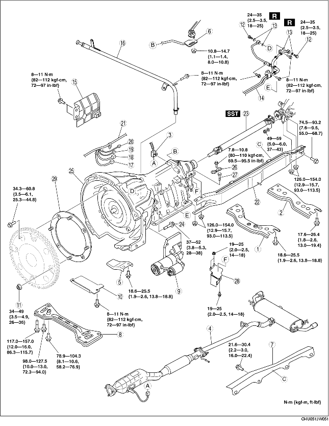
1
Front tunnel member
2
Rear tunnel member
3
Heated oxygen sensor connector
4
Catalytic converter, middle pipe, main silencer
(See EXHAUST SYSTEM REMOVAL/INSTALLATION.)
5
Exhaust manifold stay
6
Manual shaft lever component
(See Manual Shaft Lever Component Removal Note.)
(See Manual Shaft Lever Component Installation Note.)
7
Heat insulator
8
Transverse member
9
Starter
(See STARTER REMOVAL/INSTALLATION.)
10
Under cover
11
Torque converter installation nuts
(See Torque Converter Installation Nuts Removal Note.)
(See Torque Converter Installation Nuts Installation Note.)
12
Connector bolt
13
Washer
14
Oil pipe, oil hose
(See OIL COOLER REMOVAL/INSTALLATION (AT).)
15
Insulator
16
Oil filter tube, Dipstick
17
TR switch connector
18
Solenoid valve connector
19
VSS connector
20
Turbine sensor connector
21
Wire
22
Power plant frame
(See Power Plant Frame Removal Note.)
(See Power Plant Frame Installation Note.)
23
Propeller shaft
(See Propeller Shaft Removal Note.)
(See PROPELLER SHAFT REMOVAL/INSTALLATION.)
24
Transmission installation bolt
25
Transmission
(See Transmission Removal Note.)
(See Transmission Installation Note.)
26
Stopper
27
Bolt
28
Dynamic dumper
29
Driven plate
2. Remove the manual shaft lever component installation nut.
2. Remove the torque converter installation nuts using a SST.
Note� After separate the transmission from engine, remove the driven plate.3. Loosen the driven plate installation bolts.

2. Remove the power plant frame.
2. Insert a slab of wood behind the differential and remove the propeller shaft.

2. Remove the transmission installation bolt.

2. Install the driven plate to the transmission (torque converter), and temporarily tighten.
3. Tighten the transmission mounting bolts.
Bolt lengthA: 55 mm {2.2 in}B: 90 mm {3.5 in}Tightening torque37-52 N�m {3.8-5.3 kgf�m, 28-38 ft�lbf}
2. Install the power plant frame.
3. Temporarily tighten the nuts in the order shown in the figure.
4. Tighten nut 1 until the power plant frame is seated in the differential.
5. Install the heat insulator, exhaust manifold stay, catalytic converter\main silencer and front tunnel member.
6. Raise the front end of the power plant frame (transmission side) with the transmission jack and adjust dimension A to the standard (lower end of power plant frame-lower end of the front tunnel member) as shown in the figure.
Standard dimension A48.4-56.4 mm {1.91-2.22 in}Note� When raising the power plant frame without a transmission jack, use bolts (M12x1.25) with a thread length of 55 mm {2.2 in} or more. Tighten the bolts from the underside of the front tunnel member as shown in the figure and raise the power plant frame.� When using bolts, the underside of the power plant frame could be damaged. Affix tape to the underside of the frame to prevent damage.7. Tighten the nuts and bolts on the differential side in the order shown in the figure.
Bolt, nut number
Tightening torque (N�m {kgf�m, ft�lbf})
1, 2 126.0-154.0
{12.9-15.7, 93.0-113.5}
3 74.5-93.2
{12.9-15.7, 55.0-68.7}
8. Tighten the nuts on the transmission side in the order shown in the figure.
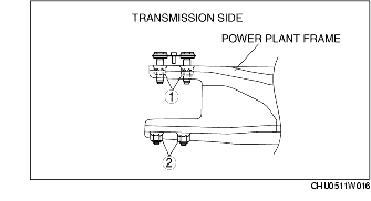
Tightening torque126.0-154.0 N�m{12.9-15.7 kgf�m, 93.0-113.5 ft�lbf}9. Verify again that dimension A is within the specification.
� If not within the specification, adjust dimension A again.
2. Lock the drive plate using a flathead screwdriver.
Caution� Loosely and equally tighten the torque converter nuts, then further tighten them to the specified tightening torque.3. Tighten the torque converter installation nuts.
Tightening torque34-49 N�m {3.5-4.9 kgf�m, 26-36 ft�lbf}

2. Install the manual shaft lever component installation nut.
Tightening torque10.8-14.7 N�m{1.1-1.4 kgf�m, 8.0-10.8 ft�lbf}
2. Remove the battery cover.
3. Disconnect the negative battery cable.
4. Drain the ATF. (See AUTOMATIC TRANSMISSION FLUID (ATF) REPLACEMENT.)
5. Remove in the order indicated in the table.
6. Install in the reverse order of removal.
7. Add ATF and, with the engine idling, inspect the ATF level and inspect for leakage. (See AUTOMATIC TRANSMISSION FLUID (ATF) REPLACEMENT.) (See Automatic Transmission Fluid (ATF) Level Inspection.)
8. Inspect selector lever operation. (See SELECTOR LEVER INSPECTION.)
9. Inspect for leakage of ATF from all connecting points.
10. Perform the mechanical system test. (See MECHANICAL SYSTEM TEST.)
Service item
Test item
Line pressure test
Stall speed test
Time lag test
Automatic transmission replacement
�
Automatic transmission overhaul
�
�
�
Torque converter replacement
�
�
Oil pump replacement
�
Clutch system replacement
�
�
11. Perform the road test. (See ROAD TEST.)
1
Front tunnel member
2
Rear tunnel member
3
Heated oxygen sensor connector
4
Catalytic converter, middle pipe, main silencer
(See EXHAUST SYSTEM REMOVAL/INSTALLATION.)
5
Exhaust manifold stay
6
Manual shaft lever component
(See Manual Shaft Lever Component Removal Note.)
(See Manual Shaft Lever Component Installation Note.)
7
Heat insulator
8
Transverse member
9
Starter
(See STARTER REMOVAL/INSTALLATION.)
10
Under cover
11
Torque converter installation nuts
(See Torque Converter Installation Nuts Removal Note.)
(See Torque Converter Installation Nuts Installation Note.)
12
Connector bolt
13
Washer
14
Oil pipe, oil hose
(See OIL COOLER REMOVAL/INSTALLATION (AT).)
15
Insulator
16
Oil filter tube, Dipstick
17
TR switch connector
18
Solenoid valve connector
19
VSS connector
20
Turbine sensor connector
21
Wire
22
Power plant frame
(See Power Plant Frame Removal Note.)
(See Power Plant Frame Installation Note.)
23
Propeller shaft
(See Propeller Shaft Removal Note.)
(See PROPELLER SHAFT REMOVAL/INSTALLATION.)
24
Transmission installation bolt
25
Transmission
(See Transmission Removal Note.)
(See Transmission Installation Note.)
26
Stopper
27
Bolt
28
Dynamic dumper
29
Driven plate
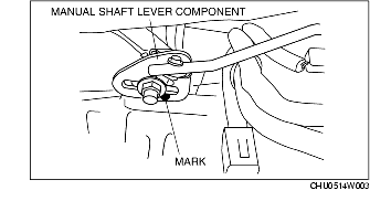
Manual Shaft Lever Component Removal Note
1. Mark the manual shaft lever component as shown in the figure.2. Remove the manual shaft lever component installation nut.
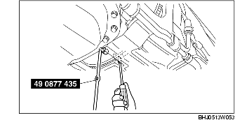
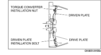
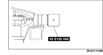
Torque Converter Installation Nuts Removal Note
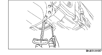
1. Lock the drive plate using a flathead screwdriver as shown in the figure.2. Remove the torque converter installation nuts using a SST.
Note� After separate the transmission from engine, remove the driven plate.3. Loosen the driven plate installation bolts.
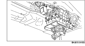
Power Plant Frame Removal Note
1. Support the transmission using a transmission jack.2. Remove the power plant frame.
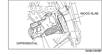
Propeller Shaft Removal Note
1. Install the SST to the output shaft.2. Insert a slab of wood behind the differential and remove the propeller shaft.
Transmission Removal Note
Warning� Verify that the transmission is securely supported by the jack. If the transmission falls, serious injury or death and damage to the vehicle could result. Before removing the transmission make sure that the jack is securely supporting the transmission.Caution� To prevent the torque converter and transmission from separating, remove the transmission without tilting it toward the torque converter.1. Support the transmission securely using a transmission jack.2. Remove the transmission installation bolt.
Transmission Installation Note
Warning� Verify that the transmission is securely supported by the jack. If the transmission falls, serious injury or death and damage to the vehicle could result. Before removing the transmission make sure that the jack is securely supporting the transmission.Caution� To prevent the torque converter and transmission from separating, remove the transmission without tilting it toward the torque converter1. Support the transmission securely using a transmission jack.2. Install the driven plate to the transmission (torque converter), and temporarily tighten.
3. Tighten the transmission mounting bolts.
Bolt lengthA: 55 mm {2.2 in}B: 90 mm {3.5 in}Tightening torque37-52 N�m {3.8-5.3 kgf�m, 28-38 ft�lbf}
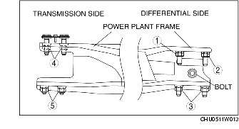
Power Plant Frame Installation Note
1. Support the transmission and differential so that they are level using a transmission jack.2. Install the power plant frame.
3. Temporarily tighten the nuts in the order shown in the figure.
4. Tighten nut 1 until the power plant frame is seated in the differential.
5. Install the heat insulator, exhaust manifold stay, catalytic converter\main silencer and front tunnel member.
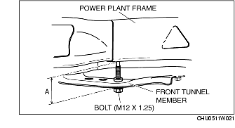
6. Raise the front end of the power plant frame (transmission side) with the transmission jack and adjust dimension A to the standard (lower end of power plant frame-lower end of the front tunnel member) as shown in the figure.
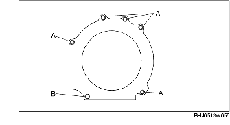
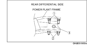
Standard dimension A48.4-56.4 mm {1.91-2.22 in}Note� When raising the power plant frame without a transmission jack, use bolts (M12x1.25) with a thread length of 55 mm {2.2 in} or more. Tighten the bolts from the underside of the front tunnel member as shown in the figure and raise the power plant frame.� When using bolts, the underside of the power plant frame could be damaged. Affix tape to the underside of the frame to prevent damage.7. Tighten the nuts and bolts on the differential side in the order shown in the figure.
Bolt, nut number
Tightening torque (N�m {kgf�m, ft�lbf})
1, 2 126.0-154.0
{12.9-15.7, 93.0-113.5}
3 74.5-93.2
{12.9-15.7, 55.0-68.7}
8. Tighten the nuts on the transmission side in the order shown in the figure.
Tightening torque126.0-154.0 N�m{12.9-15.7 kgf�m, 93.0-113.5 ft�lbf}9. Verify again that dimension A is within the specification.
� If not within the specification, adjust dimension A again.
Torque Converter Installation Nuts Installation Note
1. Align the holes by turning the torque converter.2. Lock the drive plate using a flathead screwdriver.
Caution� Loosely and equally tighten the torque converter nuts, then further tighten them to the specified tightening torque.3. Tighten the torque converter installation nuts.
Tightening torque34-49 N�m {3.5-4.9 kgf�m, 26-36 ft�lbf}
Manual Shaft Lever Component Installation Note
1. Align the mark of the manual shaft lever component as shown in the figure.2. Install the manual shaft lever component installation nut.
Tightening torque10.8-14.7 N�m{1.1-1.4 kgf�m, 8.0-10.8 ft�lbf}

Thread
Thread Starter
Forum
Replies
Last Post