
DIY: Turbo Timer Install

Thread Starter
Registered User
Joined: Mar 2005
Posts: 531
Likes: 1
From: Topsail Island, NC
DIY: Turbo Timer Install w/ Working Factory Alarm
Also reference this thread for the written instructions I am following: https://www.rx8club.com/showthread.p...d=1#post982718 A Big thank you to the modsquad for providing the written instructions.
I started on the install tonight but it was getting late so I hopefully will have it finished in the next couple of nights, I will add to it as I get it done.
I used the Apexi Auto timer (pen sized) namely for two reasons, the size mostly and it also has a/f ratio functions which I will research later for when I get my sensor installed.
I decided to mount in the ash tray for concealment.
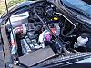
Step 1 and Pic 1: Remove the center console top by removing the little plug inside the console on the passenger side and lifting the top up. Unclip any nav plugs or heated seat plugs and unscrew gear shift ****. Remove the two screws holding the ash tray and pull up and out to disconnect ash tray. Remove the plugs on back side of ash tray so that you can totally remove the ash tray from the car.
I started on the install tonight but it was getting late so I hopefully will have it finished in the next couple of nights, I will add to it as I get it done.
I used the Apexi Auto timer (pen sized) namely for two reasons, the size mostly and it also has a/f ratio functions which I will research later for when I get my sensor installed.
I decided to mount in the ash tray for concealment.
Step 1 and Pic 1: Remove the center console top by removing the little plug inside the console on the passenger side and lifting the top up. Unclip any nav plugs or heated seat plugs and unscrew gear shift ****. Remove the two screws holding the ash tray and pull up and out to disconnect ash tray. Remove the plugs on back side of ash tray so that you can totally remove the ash tray from the car.
Last edited by zoomzoom_8; Aug 1, 2005 at 12:01 AM.
Thread Starter
Registered User
Joined: Mar 2005
Posts: 531
Likes: 1
From: Topsail Island, NC
Step Two:
Remove the ashtray itself from the ash tray housing and the ash tray door by gently prying one hinge outward until it releases. You will need to cut in the right hand ridge (nearest the cig lighter) with a dremel or like tool a groove for the turbo timer to sit in. Pics follow.
Remove the ashtray itself from the ash tray housing and the ash tray door by gently prying one hinge outward until it releases. You will need to cut in the right hand ridge (nearest the cig lighter) with a dremel or like tool a groove for the turbo timer to sit in. Pics follow.
Thread Starter
Registered User
Joined: Mar 2005
Posts: 531
Likes: 1
From: Topsail Island, NC
The first picture is of the groove cut in the ridge near the cig lighter, the second is on the opposite end, a hole cut for the corner of the turbo timer to sit in.
Trust me, I know the hole on the left side looks messy BUT you will know why when you try to get the dremel in there and I was using the flexi on the dremel!
Nevertheless, the messy hole is hidden very well when finished so it will be a dirty little secret soon enough.
Trust me, I know the hole on the left side looks messy BUT you will know why when you try to get the dremel in there and I was using the flexi on the dremel!
Nevertheless, the messy hole is hidden very well when finished so it will be a dirty little secret soon enough.
Thread Starter
Registered User
Joined: Mar 2005
Posts: 531
Likes: 1
From: Topsail Island, NC
Step three:
Buy some two part epoxy from the local auto store or wal-mart. mix according to instructions and smear a little on the ridge and bottom of timer where it will rest. Be sure to place the opposite end of timer in the hole on the opposite end. Working from underneath the ash tray housing, smear some epoxy all around the hole and the corner of the timer that will be exposed underneath.
Drill a hole for the turbo timer wire to run into the dash area with a standard drill. Route wire through the hole being careful not to damage the plug on the end. I made my hole a little small but was able to work the plug through, just be careful.
Thread Starter
Registered User
Joined: Mar 2005
Posts: 531
Likes: 1
From: Topsail Island, NC
Step Four:
Re-install the ash tray assembly and route wire from turbo timer underneath head unit and out into dash area under driver side.
This is where I will pick up from tomorrow. Pics below show the turbo timer mounted in my 8!
Re-install the ash tray assembly and route wire from turbo timer underneath head unit and out into dash area under driver side.
This is where I will pick up from tomorrow. Pics below show the turbo timer mounted in my 8!
Thread Starter
Registered User
Joined: Mar 2005
Posts: 531
Likes: 1
From: Topsail Island, NC
Just wanted to post an update on the project in case anyone was really waiting to see more. Worked most of the evening on it, got the ignition tapped, and the relay to bypass the keysensing of the factory alarm installed. turbo timer comes on and does its countdown when the engine cuts off but the engine cuts off  So going to do some research and hopefully will have it figured out tomorrow night. One of two things, the written instructions were written from memory and they state to tap a yellow/black wire. In the ignition area, there are two wires that could easily be confused a black w/yellow stripe and a yellow w/black stripe. Second it may be the relay i bought but I am trying now to just get the turbo timer to keep the engine running and will worry about that later. If anyone out there knows which wires are ignition 1 and ignition 2 please feel free to chime in! Be back tomorrow night with update and hopefully sucessful pics!
So going to do some research and hopefully will have it figured out tomorrow night. One of two things, the written instructions were written from memory and they state to tap a yellow/black wire. In the ignition area, there are two wires that could easily be confused a black w/yellow stripe and a yellow w/black stripe. Second it may be the relay i bought but I am trying now to just get the turbo timer to keep the engine running and will worry about that later. If anyone out there knows which wires are ignition 1 and ignition 2 please feel free to chime in! Be back tomorrow night with update and hopefully sucessful pics!
Thread Starter
Registered User
Joined: Mar 2005
Posts: 531
Likes: 1
From: Topsail Island, NC
Okay, to pick up where I left off, the timer is installed now to connect to the ig1 and ig2 wires. Remove the steering column cover by unscrewing the three screws located on the bottom of the column. Gently lift or pry the top up and it will release, remove it and gently pull the bottom down until it is removed. There are of course lots of wires but the ones we need at located on the driver side on the back (in pictures). Prepare the Turbo timer harness, I used the spade type connectors and attached them to the prongs of the turbo timer plug (see picture) Make your blue wire (ig 2) longer, you will have to route it to the passenger side later. Connect the green (yellow on mine, did not have green wire) to the Black and yellow wire and the red (12v constant) to the yellow wire on the ignition harness (it loops from and back into the igntion harness). You can verify that the looped yellow wire is the right one by testing it with a common light probe.
Thread Starter
Registered User
Joined: Mar 2005
Posts: 531
Likes: 1
From: Topsail Island, NC
Now on the turbo timer relay you should have three wires(depending on your turbo timer). On the Apexi, the white wire is the 02, black is ground and gray is the parking brake switch that kills the engine if the parking brake is released. Run the gray (parking brake) wire to the center console and tap it into the only wire coming from the parking brake switch. I grounded the ground wire to a bolt near the parking brake for the time being. To use advanced features of the turbo timer like auto idle and 02, the ground needs to be ran to the ground on the ecu, that is for another installment. (pic is of parkng brake connect)
Thread Starter
Registered User
Joined: Mar 2005
Posts: 531
Likes: 1
From: Topsail Island, NC
Now on the passenger side of the car, remove the door trim plate and the kick panel at the bottom. The black box up by the heater blower is the brain for the factory alarm. Remove it by pushing up gently, pull the wiring harness from the metal bracket to give you some room to work with. Look for the black/yellow wire that we tapped in the ignition part of this DIY. Cut it in to! Put a crimp on slide like the ones in the picture on both ends. Also take the blue wire from the turbo timer harness and put one of these slides on there too. Connect to a common relay as follows: the black yellow wire connect to pin 30 of the relay and the other side to pin 87a. Pin 86 is a ground, run a ground wire to the ground panel below (very easy to see). Hook the blue wire to pin 85. Now test out the turbo timer by cranking the engine, letting in run a while to not flood (although mine never floods), put the parking brake on and turn off ignition and remove the key. Engine should still be running until turbo timer cuts it off. Disregard the picture of the relay because at this stage, my turbo timer works although I still cannot arm the alarm system until the engine cuts off. I have a problem with the relay, picked up the wrong one. I will post the correct one on here tomorrow night. With the correct relay, it is easy to bypass the alarm and be able to arm it while the engine is running.
Zip tie your harness in place and secure the alarm brain, install kick panel and sill plate. Re-install center console and you should be good to go.
Zip tie your harness in place and secure the alarm brain, install kick panel and sill plate. Re-install center console and you should be good to go.
Thread Starter
Registered User
Joined: Mar 2005
Posts: 531
Likes: 1
From: Topsail Island, NC
Hey RX-8'rs,
i'm gonna go on memory, but this should get ya going....
start by mounting it up i guess, check the pic, if you wanna sacrifice your ashtray, it makes for an awesome place and can be covered for stealthness. just be careful, cut the hole nice and tight with a dremel, then i used epoxy from behind to hold it solid to the plastic, looked super good!!!
for the wiring, the e-brake wire is easy to find, when you pop off the trim for the centre console, the wire is very obvious running from the switch on the ebrake.
apparently there is no tach singal that can be used on the RX-8, so i wasn't able to hook up the RPM monitoring feature of the HKS type0 TT.
finding a ground is pretty straight forward, just put a ring terminal on the end of the black wire and hook it upto a bolt that goes into the metal frame of the dash or body.
for the ignition connections, the RX8 uses a low current ignition, but the miniscule amount of power drawn by the electronics on the TT should not over draw the system, just be careful if you are hooking up other stuff to the ignition connections, like gauges and boost controllers, you should run a relay and have the power fused and directly connected to the battery.
you'll have to take the plastic housing off the steering coloum to access the ignition connections....
run the red (+) wire from the turbo timer and connect it to the yellow wire at the ignition switch, to test to make sure it's the right wire, test for +12v on it at all times
run the green (+ ign) wire from the turbo timer and connect it to the black/yellow wire at the ign switch, to test it should have +12v on it only when the key is in the on position or in the start position.
the last wire, blue (+ accessory) wire, is not connected to the ignition, it will be run behind the dash and over to the passenger side kickpanel, keed that in mind for now and read on.......
you will need to get a standard relay and harness or 4 connectors, search the net for more info on relay hookup at a site called the12volt.com if you are unsure about relays, it's really easy tho, the terminal numbers are on the bottom of the relay beside the pins so it should be straight forward even for beginners.
to get to the factory alarm module you will need to take the glove box out, accomplished by squeezing it together at the back and rotating it forward until it's almost touching the floor, then it pulls straight out. then remove the door sill trim and passenger kickpanel.
way up on the side beside the heater motor mounted against the body is the factory alarm, you can press lock on your factory remote and hear the relays clicking inside the brain to help locate it. to get it down, you have to pull a connector and wiring harness off the metal bar they are mounted to, then remove one 10mm nut holding that bar to the firewall and a phillips screw at the front of the bar. they are tricky to get to, you will need some swivels and some patinece to get it all apart. pull the module down, and in on of the harnesses there will be a black/yellow wire. this is the ignition input to the factory alarm that stops the alarm from being able to be armed while your key is turned to the on position. there is also a key sense wire that was pink/(some colour, black or blue, can't remember). you don't need this wire for anything, but if you are interested in the theory for testing, even after you cut that black/yellow wire, you still can't arm the system wit h the key in the ignition because of the keysense wire, so don't think that something is wrong after you cut the wire and can't arm the alarm with the key in, it will work with the turbo timer properly after you are finished up the install.....
continuing on, that black/yellow wire at the alarm brain, cut it in half. now connect pin 87a of the relay to one side of the black/yellow wire and pin 30 of the relay to the other side of the black/yellow wire, it doesn't matter what the order is, all this does is open up the ignition signal from going into the alarm brain when the TT is active.
now connect pin 86 of the relay to ground, there is a collection of ground wires in that kickpanel going to a common ground point, you can just bare any of them and hook into it for a good solid ground signal and save yourself a ring terminal, or just bolt it to ground.
for the last connection, that + accessory wire (blue) from the TT, hook it up to pin 85 of the relay. this causes the relay to activate when the TT is active, and opens up the ignition sigal from getting to the alarm brain, therefore allowing the alarm to be armed while your car runs and cools off.
just clean everything up with some zip ties and put all the panels back. everything should be working peachy now, hope these instructions are useful for the connections and some theory behind why this works....if you find any errors or problems with it, please let me know at modsquad@shaw.ca so i can correct it and also try to find a solution. you can ask me any questions too at that address and i'll try to help you out....
The above are the written instructions, I am still having trouble with the relay and the black/yellow wire. The tt works great, just can't arm the system, I have tried two different relays. I am still working on it, anyone want to glance at the wiring schematics that are better than I am? I have the black yellow wire connected, relay grounded and the ig2 wire connect to relay. If the black yellow is not connect to relay, tt does not work and car does not start. Please pitch in, I am beginning to think maybe something was left out on the instructions above.
Thread Starter
Registered User
Joined: Mar 2005
Posts: 531
Likes: 1
From: Topsail Island, NC
Just an update, turbo timer stills works great, looks great. trying to solve the stock alarm problem. order a relay as no one at any parts store around here knew what to look for and the one off the counter did not work. I will update when i get it working with the stock alarm and put part number on here and call it another finished job.
Thread Starter
Registered User
Joined: Mar 2005
Posts: 531
Likes: 1
From: Topsail Island, NC
okay everyone, finally finished this DIY. I think I have found a cool way to get around the stock alarm to allow it to arm while the engine is running. So here goes:
The black/yellow wire at the alarm brain is already cut into. It is supposed to hook to the relay and when the relay sense the current from the tt, it breaks the black/yellow connection thus tricking the ecu that the engine is not running and allowing you to arm the alarm. this was the part i could not get to work, even after buying another relay and trying it.
Tell you about my testing first in case someone else does not like how i did this, you will have some background info to work your fix.
With the car running on the turbo timer, there is current running from the tt as I expected (the blue wire). there is also current coming from the black/yellow wire. The test light glowed very dim on both, low voltage ignition and low voltage tt. I suspect the reason i could never get the relay to work is because it is a 30 amp relay and maybe the tt does not send enough power to trip the relay and break the black/yellow connection. So when the car is running on the tt only with no key, I unhooked the black/yellow wire to simulate a break in connection by the relay. the factory alarm would then arm with no problem. But if you leave that b/y wire unhooked, the car will not start again.
So this was my work around. I have some DIY switches on the lower trim plate of the radio and am only using one of the three installed. i wired two wires from the the cut b/y wire to the switch and of course grounded the switch itself to a common ground wire I ran months ago. So now, i flip that switch to the on position, start the car and off I go. When I stop the car, I turn that switch off, put the e-brake on, and take the key from the ignition. the car continues to run by the tt. Arm the alarm and it works like a charm. this is the part i think i like the most though. When I get back in the car and try to start it, it will not start! I have to turn that switch back on and then the car starts like normal. So my theory on that is that if someone ever tries to steal the 8, I basically have an unlabeled iginition kill switch too.
The blue wire from the tt is still hooked to the relay and the relay is still grounded. did not try it with the blue wire unhooked so not sure what is going on there.
But everything is working great for me like this.
If you don't like my way, investigate a lower amp relay and connect it per the above instructions and it just may work like it is supposed to.
Happying Boosting!


Thread Starter
Registered User
Joined: Mar 2005
Posts: 531
Likes: 1
From: Topsail Island, NC
**** UPDATE ******
Now solved the relay problem. Theory is that the tt did not have enough power to energize the relays coil and flip the switch in the black/yellow wire. I found a relay on ebay that took low current to energize the coil and flip the switch.
Here is the relay's specifications:
Rating: 12V DC
Type: SPDT: Single Pole Double Throw
Coil Resistance: 90 Ohms
Coil Inductance 0.8H
Dielectric Strength: 500V RMS
Electrical Life: 10 Million operations
Temperature Range -40�C ~ 125�C
Inital Operating Data 7 milliseconds
(picture is attached, came with a harness also)
So connect your wires as follows:
Blue Wire from TT connects to pin 86 (white wire on harness)
Ground connects to pin 85 (black wire on harness)
One side of Black/Yellow wire connects to pin 30 (blue wire on harness)
Other side of black/yellow wire connects to pin87a (red wire on harness)
pin 87 (yellow wire on harness) is left unconnected.
Tuck all this back into the space, replace trim panel and sill plate.
Start car, remove key, engine runs because of tt, shut doors, press lock twice, horn blows, alarm set!
So two ways to do this:
1) Kill Switch for black/yellow wire (although idle seems to be rough on mine when used, not sure if will happen on yours.)
2) Use this relay with no kill switch.
Happy Boosting!
Thread Starter
Registered User
Joined: Mar 2005
Posts: 531
Likes: 1
From: Topsail Island, NC
okay last installment on this diy, if you remember with the apexi tt, when the car was warm and the tt kicked in, it idle very bad and actually blew black smoke! never could figure out what was wrong but i figured out how to fix it.
Splice into or use a wire tap on the wire that goes to the ignition from the tt with a short "jumper" wire. Connect the other end of the jumper wire to the white/red accessories wire in the ignition bundle where you have the other wire connected to the yellow one. tape it all up for safety and bingo, tt works perfectly.
I noticed that when the ignition was off, i got the bad idle but as soon as i switch the key to the accessories on position, the idle smooth out. So all this fix does is keep the accessories wire hot while the tt is on allowing you to remove the key, lock the doors and go about your business.
THIS DIY IS COMPLETE, The apexi tt pen sized will work on the 8!

Riot Controller
Joined: Jan 2004
Posts: 2,142
Likes: 0
From: Orlando, FL
Installed my HKS timer today. All went well (although i do wish i bought a bigger car lol), but I cannot for the life of me get anywhere near that immobilizer box. PUR NRG suggests only removing the harnesses, and I see now you removed the entire box to get to the ignition wire..
Could you by any chance give a little more detail on how to get that box down out of there?
I installed mine behind the glovebox, so it may be worth mentioning that when you tap the wires on the ignition cylinder, it's best to run them under the HVAC unit if the timer is going to reside anywhere on that side of the car. There's about enough room under there to get your hand through, and be sure and tie the wires off so that they don't make love with you toes while you're doing your magic on the pedals.

NW Florida TURBO
Joined: Feb 2008
Posts: 283
Likes: 1
From: Navarre FL, In my boosted 8...
hey how did you hook up the O2 wire, cause i have s straight pipe so my CEL is always on cause of the O2 sensor. but I'm about to put in a widband as well would it be possible to just hook the O2 wire and ground to the widband signal instead of the ECU signal ?????
NW Florida TURBO
Joined: Feb 2008
Posts: 283
Likes: 1
From: Navarre FL, In my boosted 8...
OK here some some good info for those who need to do this install and don't whant to have to kut like four diferent wire just to find out witch one it is that runs to the relay everything on this link is correct and accurate you won't need a switch or any special relay have fun http://images.google.com/imgres?imgu...%3Den%26sa%3DN

what a wankel!
Joined: Dec 2006
Posts: 165
Likes: 0
From: Sydney
A couple of links regarding the making the Apexi TT read AF via the O2 sensor that I found useful:
http://www.innovatemotorsports.com/f...hread.php?t=77
http://www.innovatemotorsports.com/f...hread.php?t=54
http://www.innovatemotorsports.com/f...hread.php?t=77
http://www.innovatemotorsports.com/f...hread.php?t=54

Registered
Joined: Mar 2008
Posts: 54
Likes: 0
From: NY
cant we just find where the o2 sensor wire is on the ecu and connect the tt 02 sensor wire to the o2 sensor wire that goes to the ecu?? there would deff have to be some extention to be made but it would work no? and i thought thats what the original instructions were saying to do but they didnt have rx8 listed for the ecu cause they are a bunch of dumb ****** and decide that a honda oddesy would get a turbo timer set up and not an rx8. makes sence right? lol