When you click on links to various merchants on this site and make a purchase, this can result in this site earning a commission. Affiliate programs and affiliations include, but are not limited to, the eBay Partner Network.
Not sure why; the original PDF files are uploaded on the forum and still work fine. I�ll try to convrt to jpg images.
But to answer your question, which was addressed in the first post, it won�t anything meaningful at 58 psig because the relief valve blows off at 50 psig. You have to understand that the OE test is for all intents and purposes a dead-head test. When you try to force everything through the bypass it�s essentially dead-heading because the bypass can�t flow anywhere near the actual capacity of the pump. Even at idle the fuel flow to the engine is so low that it will do the same.
However, at 50 psig it was tested at 46.5 gph @ 13.5 Volts. At the std 45 psig injector rating it�s around 54 gph
No, you have to understand that the fuel demand for the OE engine is much lower than the noted test output flow measurements. If you notice on the report they state that the bypass starts cracking before 50 psig at the lowest noted flowrate. Without a lot of complicated BS they don’t have any way to measure what is going through the bypass valve. Now they could have cranked the output flow back to an estimated maximum OE rating, but without knowing what is going through the bypass in addition to that they have no way of knowing what the actual total pump output is.
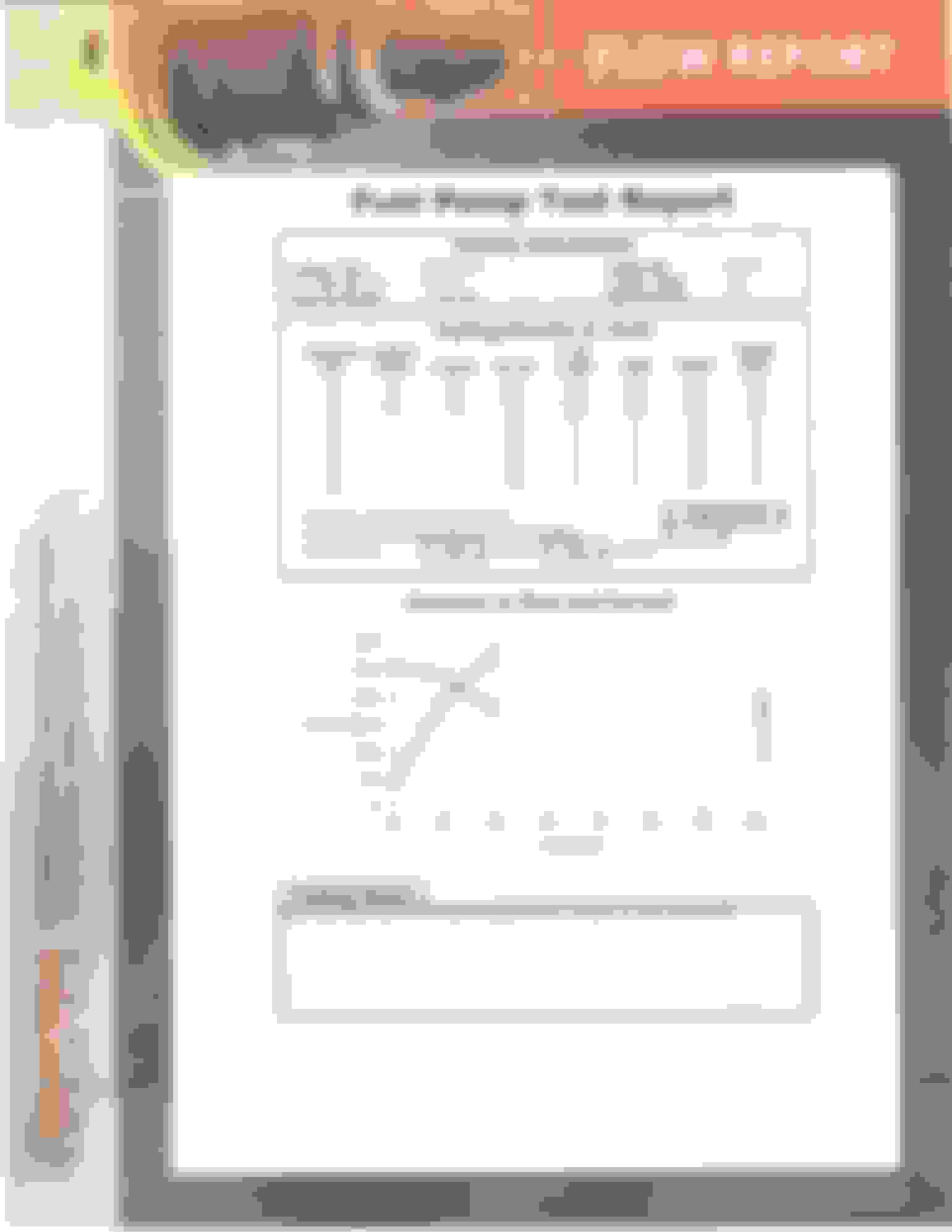
Here is what they test for:
DW is committed to high quality products and excellent customer service. All products are backed up with a 3-year comprehensive warranty. This warranty could not be offered without supreme confidence in product quality. As part of QA procedures all pumps and all injectors are bench tested in-house before packaging and shipment to the customer. Below is a brief over of the fuel pump testing process…
High and low pressure flow
Amperage draw vs flow
PRV activation point
Check valve function
Cavitation check
Qualitative observations
That said they do offer a graph for their base 265LPH 65C pump that fits the module and you can assess a total output at 58 psig, but again you have no way of being sure what is going to the fuel rail vs. what is being bypassed. It appears to be approx. 238LPH (69 GPH)
However the actual once installed in the pump module is different because it’s a brand new pump (as opposed to a nominal guaranteed rating), has to actually pump through the filter and various other internal restrictions, had some bypass actually occuring at the 50 pdig rsting, and so on:
If they had contacted me during the test I might have asked them to assess an output fuel flow by blocking the output to achieve 58 psig, but I only received the results after the testing was completed. Now if you want to pay for it I can send the OE pump back to them and ask that it be tested as just a bare pump to acquire a pump only pressure vs. flow graph. It doesn’t really mean much without being installed as the difference between the two pump only vs pump module graphs above show.
The same thing applies to any aftermarket pump you install in the OE module. What is actually being achieved once installed in the module is much different than the pump-only curve from the pump manufacturer.
Still finding this confusing .........hear me out :
IMO the dropoff in flow from 40 psi on is from the siphon , not the PRV . If it was from the PRV , then the pressure would never reach 58psi when the module is on the car. The PRV is designed to make the module run at 58psi at all times. The only time it wont be 58psi (when on the car) is when the injectors are trying to flow more than the pump can output.
Assuming the pressure from the module when it's on the car is actually 58psi , then the only flow test that's relevant is with the pressure set to 58psi.
I can’t relate at all with your belief that the siphon causes that. Take your pump apart and look at the PRV. The flowpath is not only small, the PRV is also restricted internally. Even more restricted than it is the small diameter black tube that feeds the siphon (see photos in thread). They physically removed and tested the PRV. If you disagree test one yourself and see. What you say about the injectors is in fact what happens, but only because the engine demand flow is so low relative to what the pump can do vs. the module internals. However, it would take a lot of detailed testing to specifically determine what the PRV is doing, what the siphon is doing, etc. Basically the pump is flowing less than 1/2 it’s “normal” capacity at WOT on a strong NA Renesis engine.
It’s actually a common situation. This is from a discussion for an aftermarket pulse width modulation pump control system that uses fuel pressure switch for feedback to control pump speed for a constant pressure control relative to engine demand on a Chevrolet V8 engine
there is no regulator that will easily swap out and replace the CTS-V poppet valve and have an acceptable pressure curve. The 58psi regulator that does fit the CTS-V module will drop 13-15psi before full pump output is achieved. That is too much of a pressure drop to be effective in a high-output engine.
Frankly if I was going to do a significant HP setup I’d seriously consider installing an alternate pressure control or feed tank setup. For NA use it’s more than adequate, even for a 20B engine. It’s more than adequate for a moderate FI setup, but the way it’s currently setup is that you can tune for how it will operate, but the output pressure is not going to be the same across the full potential operating range as-is.
However, maybe I’m wrong/missing a piece of the puzzle. This is just the information I have now. Please contribute what you can, but let’s try to base it on factual data. I had these tests run because for years all we had were guesses and hypotheses, often passed off or accepted as fact, but no real data to back anything up.
hmmm .... I guess i'll just have to try it and see what I get . I at least have a gauge that i can watch and back off as soon as pressure starts dropping .
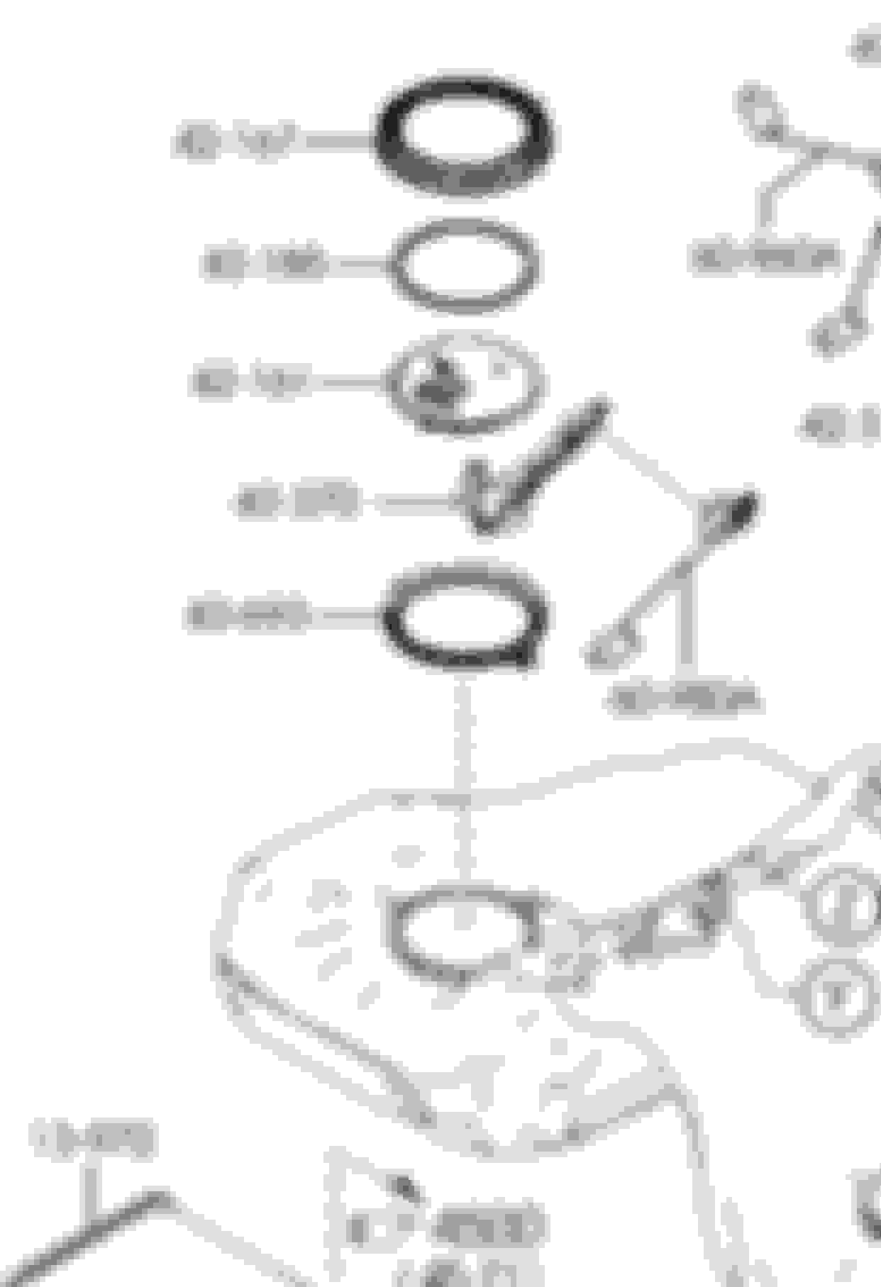
Diagram indicating the S2 fuel pump assembly parts break down. The way I interpret it, you can either buy the entire fuel pump module assembly or get it in the following partial parts (USDM part numbers on 11/16/2017)
13-280A
Part Number LFB6-13-280 PRESSURE RG (regulator)
13-350A
Part Number N3R1-13-350 PUMP,FUEL (pump only)
13-35Z
Part Number N3R1-13-35Z PUMP,FUEL (entire pump module)
13-ZE0
Part Number N3R1-13-ZE0 BODY,FUEL FILTER (main body housing,pump discharge filter, & siphon?)
13-ZE1
Part Number LFB6-13-ZE1 FILTER,FUEL PUMP (sock filter)
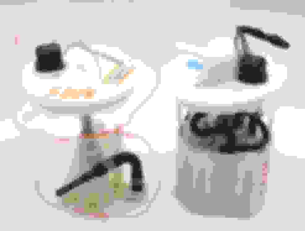
To clarify what it actually all is, here is what I received. It seems as though there are not many left and are in Canada. It DOES NOT come with a new sock, that is separate.
Top Hat
Fuel pump housing
Siphon assembly
All connected with the proper plumbing due to the fact that the hoses do not seem to be easily detached and reconnected without some fanagaling
Spring with circlip
Pump housing clip
Fuel pump nipple spacer
Pressure relief spacer
Wire harness for pump
All O rings for entire pump assembly
Basically all you need to make this a full setup would be
So there were some questions about blocking the bypass pressure regulator. If you do this it will not only block the siphon and keep it from pulling fuel from the other saddle tank, but the siphon itself will need to be blocked because it’s positioned before the bypass regulator. Blocking the bypass will result in pressure dead heading on the siphon. So you would need to add a regulator somewhere in the system and either a also add second fuel pump in the other saddle or add a new siphon/venturi setup. Which Radium sells an adjustable venturi siphon for this purpose.
Maybe a tad off topic, but definitely related... trying to understand completely the differences between the S1 and S2 fuel senders as I want to replace the whole sender in my S1 with an S2 sender.. but making sure it makes sense.
As far as the siphon valve from the right side of the tank, are the only differences between an S1 and S2 siphon sender just an internal vs external send line?? I don't see an external hose part on the OE Mazda diagrams, which is why I am asking. S2 secondhand parts seem much harder to find than S1 stuff too.
S1 Unit
S2 Unit
If that's the case, I have no issue using the S1 siphon sender and using the internal tank line. Just wondering if anyone knows before I buy parts and compare them directly myself. Seems like lots of info on one or the other, or simply putting an S2 pump in the S1 sender, but not both full systems side by side.
I seem to recall that the siphon hose between the two sides is different and you’ll need that too, but am not aware of any hose attaching there. Are you sure that piece is actually open? Because it doesn’t seem to have enough straight extension on the outer end to attach anything with those elevated ridges on there.
Looking at the Mazda EPC there’s also not any dashed line from it, which would indicate something else attaching there as well.
the one other thing is that the S2 tank is slightly different with a larger capacity and I’m not sure how all that plays out. I seem to recall that it also needs the same float level electrical connector as the S2 pump. Because that’s how I got the connector for my S2 pump swap; buying the float from that side out of an S2 part out that had already sold off the pump and connector from the other side. My memory is a bit sketchy on all that now, but I did put all those details in the S2 pump swap thread.
.
Yeah I was a bit confused at the OE diagrams... it could just be a injection mold pin or something. :shrug:
I think I'll just end up getting the sender and go from there.
I can't conceptually understand how just a pump can stop fuel sloshing issues like everyone seems to post about, so that's why I am after the full sending/siphon unit
I seem to recall it has an entirely different pickup configuration based on what the guy I bought the S2 parts from told me. Because I was going to swap over the crossover tube to avoid the connection issue at the S2 pump and he advised me against doing it without the rest of that S2 assembly. Or do you have more pictures verifying it? Because that previous photo only shows the top side. Also curious about why you’d want to change it?
I seem to recall it has an entirely different pickup configuration based on what the guy I bought the S2 parts from told me. Because I was going to swap over the crossover tube to avoid the connection issue at the S2 pump and he advised me against doing it without the rest of that S2 assembly. Or do you have more pictures verifying it? Because that previous photo only shows the top side.
I wouldn't doubt it's completely different, which kind of sucks...buuuut...
I don't think I have a photo of other parts, it seems like the "bracket" the OE Mazda site calls it is the same part number as the S1 part:
EDIT: Whoops may have highlighted both fuel level sensors
yeah, it’s entirely different, and now I want to say/recall that the siphon piece attaches to the tank floor like the float support rather than being an integral assembly with the top sealing cap like the S1 is. Which the S1 tank won’t have the mounting for. I suppose you can just use the S1 pickup instead though.
Also seem to recall that the S2 floats have a slightly different empty-full Ohm range between the two as well.
.
The removed sock rough filter and the relief valve. The relief valve has two O-ring seals. You can also see how the sock filter attachment also keeps the relief valve locked in place with attachment clips.
Who wants to spend $50 to see if this new high flow FPRV fits in an RX8 S2 pump housing?
according to the Mazda parts catalogues, the NC and S2 RX8 FPRVs are identical part numbers (LFB6-13-280), so it should fit an S2 pump module as well.
.


 10-29-2017, 05:39 PM


 It doesn’t really mean much without being installed as the difference between the two pump only vs pump module graphs above show.