When you click on links to various merchants on this site and make a purchase, this can result in this site earning a commission. Affiliate programs and affiliations include, but are not limited to, the eBay Partner Network.
Background: My partner and I bought back our first RX-8 recently, it had two owners between our periods of ownership and during that time it was subject to a lot of abuse and neglect. The last owner decided to sell it to us because he suspected the transmission was failing and during our test drive, it failed; it hasn't been able to go into gear since. There was a lot of slipping, some nasty burning smells, and a loud whining noise (not unlike a bad throw-out bearing). Nevertheless, we bought the car back, knowing very well we'd need to do something about the transmission. We already had a '05 6MT parts car, so everything was at our fingertips for this swap.
Objective: Replace the 4-speed automatic transmission with the 6-speed S1 manual transmission WITHOUT converting to a 6-port engine, reprogramming a PCM, or otherwise involving a dealership / third party.
Please refer to this thread linked here, this is already a good guide on how to get all of the drivetrain components swapped.
RotaryResurection swapped out his car's automatic transmission system, except for the dash harness. The swap I'm describing is different because we are keeping a lot of the 4-Port specific systems intact. In North America, we never received a 4-Port (Standard Power) RX-8 with a manual transmission, so unless you're sourcing a PCM and all of the other matching parts from overseas, you will need to retain the 4-Port PCM and all of the side effects that come along with that.
Preparing your engine to be mated to the 6MT is fairly simple. You will need either the stock MT flywheel or you can use an aftermarket one. If you choose aftermarket as we did, you will reuse the factory counterweight and the flywheel will bolt to that. This is easier because the bolts require much less torque than the massive nut on the eccentric shaft that secures the AT counterweight. You will also need to install a pilot bearing and seal.
The automatic RX-8s supposedly use a softer engine mount than those used in the manual, I don't think there is much of a difference in reality. I have done polyurethane filling on both types of mounts, revised mounts and those of the original design as well; the bigger difference lies between the revision and the original design. If your engine mounts are in good shape, there's no reason that I can see why you can't reuse them.
As for the steering wheel and gauge cluster, I would always retain the stock AT cluster when doing the 4-Port MT swap, otherwise, your redline on the tachometer will not be accurate. The steering wheel is entirely optional depending on your cosmetic taste, we've decided to keep it. If you do want to remove the AT paddle shifters, you do not need the whole steering wheel, you could just source the black button panels from an MT and swap those to your car's original steering wheel.
Below this post, I will outline the changes that need to be made to the wiring for the critical systems to function. I do not expect to have cruise control following this swap, this is because the car will always think that it is in neutral. I may find a workaround for this; if so, I will update the posts.
Good luck!
Last edited by Necoxus; 04-23-2023 at 06:08 PM.
Reason: grammar
The Easiest Solution(s) to Activating the AT Starter Circuit
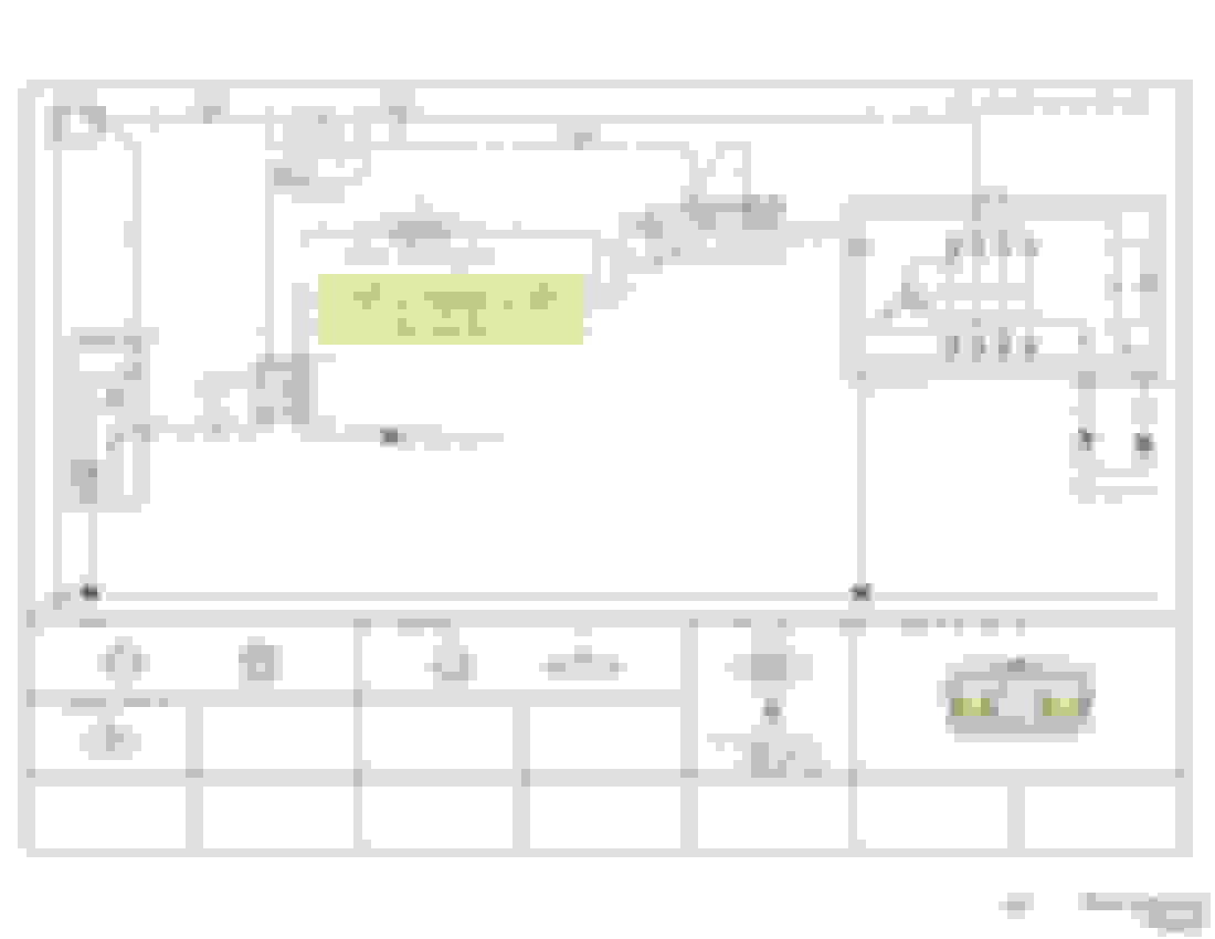
Pages 6-8 of the Workshop Electrical Manual show part of the AT Range Switch, wires LG/R and W/L become connected by the switch when either park or neutral is selected. This is a very simple circuit and it is the only piece that differs from the MT's version of the starter circuit, the diagram reflects this on the same page. Within the Range Switch the completion of the starter circuit is entirely separate from how the switch sends a signal for being specifically in park or neutral to the TCM. This means that we can complete this circuit WITHOUT the TCM knowing that we're doing so or otherwise thinking that the transmission is in a specific gear. This also means that the use of this circuit is possible even when the TCM is removed entirely, which should be helpful in a variety of applications, such as a 6-Port Manual Swap (in which the AT PCM is being replaced).
This all leads us to have a couple of options - I'm going to go over a few and then explain what I did for my specific application and why.
Option A: Splice the LG/R and W/L wires together without the use of a switch. No clutch pedal switches are required, the vehicle could be started in gear, etc.
Option B: Utilize the Neutral Switch on the MT Transmission to complete the circuit. No clutch pedal switches are required, the vehicle must be in neutral to start.
Option C: Utilize the Starter Interlock Switch (located in the rear, higher up position, on the clutch pedal assembly), you would need to run your wires through the firewall and to the engine harness where the LG/R and W/L wires are located. This one requires the most work.
I used Option B, this required no new wires to be ran through the car but still has a margin of safety as the car can't be started in gear. Which in reality is the same thing that the typical clutch pedal-mounted starter interlock switch is trying to accomplish. I cut the wires from the connector for the AT Range Switch located at the end of the engine harness and added a waterproof 2-pin connector. The neutral switch is not polarized, it is just used to complete the circuit, so I just wired the matching connector piece to its two wires. Note: We began experiencing some intermittent behavior with the neutral switch, I suspect this could be due to the contacts in the switch not liking the load that the starter solenoid draws. I would recommend that you add a relay to this circuit, you will still use the neutral switch to activate the relay, but the relay will carry a load directly from the battery to the starter solenoid.
This circuit is even more simple than the last and there is only one way that I can recommend doing this. In a 6-Port AT to MT swap, you will utilize the circuit as originally designed, assuming you are removing the TCM. The 4-Port AT to MT swap is very similar but with a small caveat concerning this circuit and the TCM.
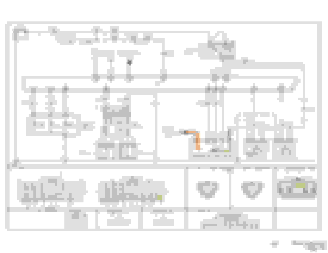
Firstly, I went to the AT Range Switch connector on the engine harness and detached the R/Y and B/Y wires. I then connected these to a two-pin marine-grade electrical connector. I then put the matching connector on the reverse switch located on the transmission. The Back-Up Light Switch used by the MT is the same as the neutral switch, in that it is not polarized and is only used to complete the circuit. (Highlighted in Yellow) Pages 60-61 of the Workshop Electrical Manual show the backup light circuit, you can see the subtle differences between the MT and AT.
------------
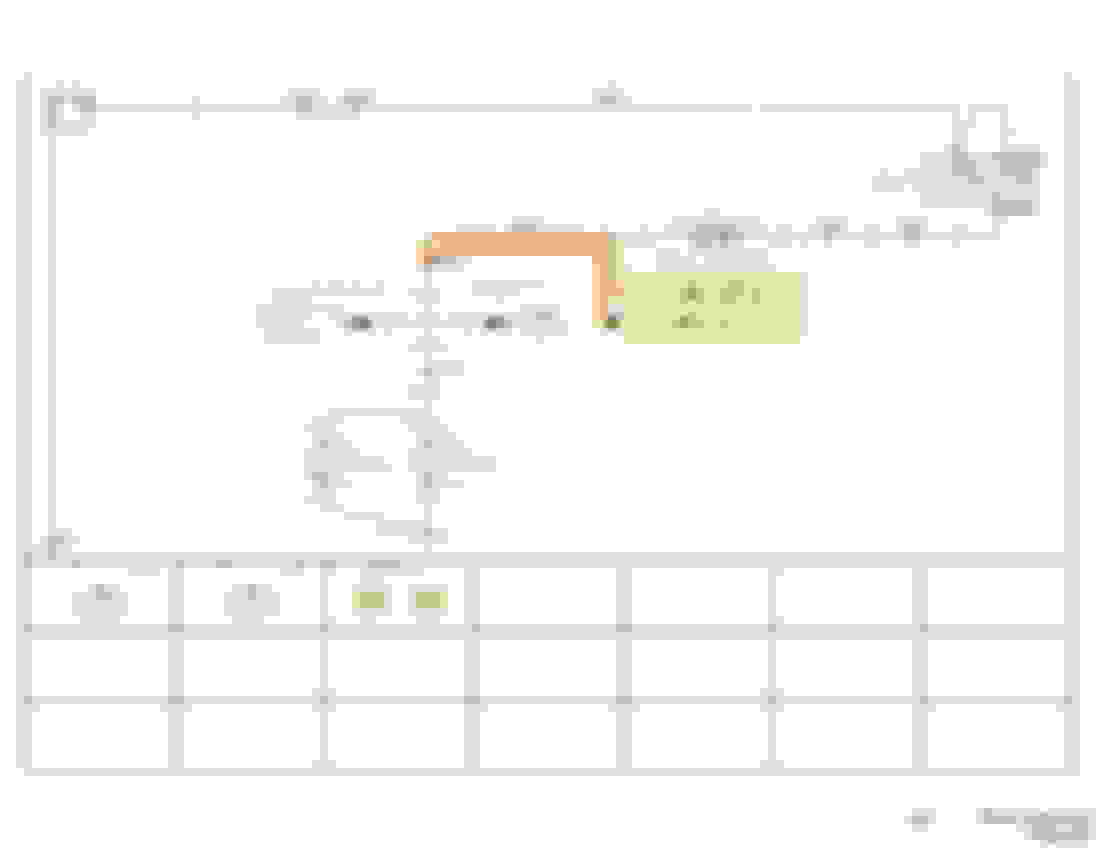
Secondly, and very importantly, we need to prevent the TCM from receiving a reverse gear signal when using the back-up light switch. This matters because otherwise the TCM will attempt to engage the reverse solenoids and find that they are missing entirely. In theory, this could set off a lot of errors with the TCM and has the potential for a limp mode condition
Located under the dash, you should at this stage already be familiar with the TCM location and have replaced its bracket with the clutch pedal assembly. Locate your electrical connectors for the TCM, the lighter colored connector that has more wires running to it is the one we're interested in. You will need to locate the R/Y wire and severe its connection, I added some liquid electrical tape to the end of this wire and bent it out of the way as an additional measure. See pages 70-71 of the Electrical Workshop Manual for the relevant connector. (Cut the wire indicated by the black bar.)
------------
Lastly, you can now secure the TCM back to its connectors and to the car. I found a hole in the clutch pedal bracket that I could fit the long stud of the TCM through and then using the original nut get it secured pretty tightly. You'll need a 10mm open-ended wrench for that. You can then attach the electrical connectors, if you try to get the TCM in place with them connected they'll just get in the way.
If you followed my instructions for the backup/reverse lights, you will find these instructions to be very similar as you are working with the same connector and wire locations.
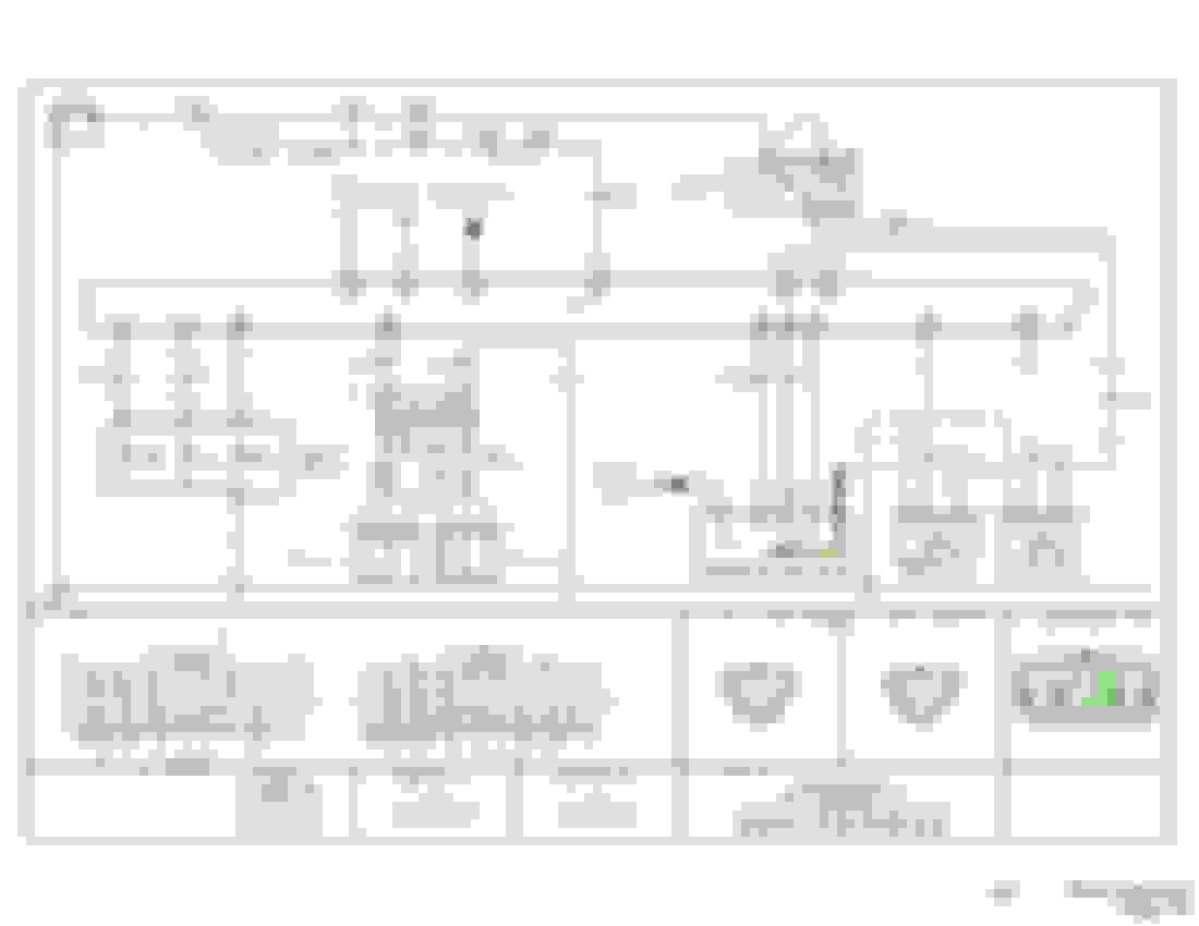
Simply, detach the O wire from the AT Range Switch connector on the engine harness and then splice it into the B/Y wire. This is the same wire that you are also using with the Back-Up Switch, so it needs to remain intact to serve that function as well. I recommend doing this higher up on the harness above where you did the aforementioned wiring. You can choose to use some sort of removing connectors so that you can undo this signal if at some point that becomes necessary; I did because to my knowledge this is the first attempt at doing this kind of swap. It should be fine to just wire them together without that precaution. The relevant circuit is shown on pages 70-71 of the Electrical Workshop Manual. (Highlighted in Green)
In this case, we want the TCM to receive the neutral signal. If the TCM were to not receive any gear selection signal, it would create a fault. I choose neutral instead of park, just because that makes more sense in case the signal is passed to other modules. It also means that the gauge cluster will illuminate the "N" light which I find to be less annoying than staring at a cluster that thinks it is in park.
Finally got the car fired up this morning for the first time since starting this swap! Everything went well, better than expected really. All of the wiring that I described above has behaved as intended.
The only transmission faults that we are currently getting are for the missing solenoids, the PCM is able to detect the incomplete circuits. A possible workaround would be to connect the solenoids and wrap them up out of the way or perhaps store them in a container with ATF. I've read of both methods being used on other manual swapped vehicles (Volvo, Mitsubishi, etc).
We connected the transmission input and output speed sensors to our harness, which is why we don't have immediate faults for them. It is possible that we will get an "out-of-range" fault once the car is driven, but hopefully it won't.
During initial road testing we encountered a limp mode type condition, so of course I was panicked thinking it was TCM related. Thankfully, it was not, after resolving an issue with our OMP the limp mode was cleared and we were able to drive around almost completely normally.
Interestingly, something about the arrangement that we chose is creating an idle hunting issue, very much like when a neutral switch fails on a stock manual transmission car. I believe that is because of some input or lack thereof that the TCM is getting, which keeps it from truly believing the neutral signal that we're sending it.
We're going to test disconnecting the TCM entirely and to see how that affects performance, it may be that without the TCM we will have a stable idle. If that fails to remedy the problem I will have to investigate further how the TCM is communicating neutral to the PCM and why it is causing the idle hunt.
Disconnecting the TCM has yeilded a stabilzed idle. I'm still interested in trying to find a better solution because without the TCM cruise control isn't functional and I believe traction control is also down, the DSC light is at least on, although there isn't a code pertaining to it (other than the CAM Bus codes).
I have devised a way to fully replicate the functionality of the AT Range Switch, using three dual pole relays and various factory MT switches, I can send apprioriate signals for all transmission states. However, I don't believe this will satisfy the TCM enough to avoid the idle issue. I'm heavily considering removing wiring harness and solenoids from old AT and seeing if I can trick the TCM with those.
We're still working on minor gremlins that are unrelated to the MT swap. One of which is an intermittent solenoid for the variable intake valve, which lead me to editing a chart from Mazda to be 4-Port specific as it is easier to digest then. We plan on adding a relay for the starter circuit, the idea is to lessen the strain on the transmission neutral switch as sometimes it fails to run the starter and we don't want to shorten the life of the switch unnecessarily. I'm also adding this note to the guide.
 04-21-2023, 01:30 AM