When you click on links to various merchants on this site and make a purchase, this can result in this site earning a commission. Affiliate programs and affiliations include, but are not limited to, the eBay Partner Network.
Thanks, good point, without resonance, its impossible to get above 100% Ve, haven't thought about that. But if you exclude the effects resonances have(who also occurs at Ve below 100%, yes), then I do not see why Ve should change massively...?
But I'm also quite sure that even at FI, resonances will occur somewhere, but even estimating this is above my league. Among other things, if density of air is increased, resonance frequency for a given length will lower. Air temp is another thing that affect a lot. As said, above me....
EDIT: Not sure what if resonance fill increase or lower, but it will change a lot with pressure, density and temperature.
Again you have some good points that I failed to read through and assess correctly. Apparently I need to follow my advise to Brettus and lay off the hair trigger responses myself ...
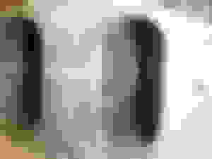
The ID is 2.067� which is actually just a fraction larger on circumference than the port.
Then we perfectly agree, rest of the post is a massive over- interpretation of my post I was only talking about keeping as much as possible of the pulse energy for the turbine to harvest, not waste them in the pipeline, nothing more.
By the way, I've dug myself quite deep down in the audio hole for a couple of decades(ref previously mentioned "other industry"), there are a fascinating many similarities between NA intakes/exhaust and horn speakers. So I hope you don't mind, just for to spice up, here is one project I was involved in, that also is a bit extreme. I guess its the equivalent to a optimized variable low RPM ship engine NA intake:
Could not get rest before I checked, the 7000RPM limit, and a slight reduction in Ve seems to make a big difference as well, without the resonances, I would expect that Ve is reduced, and maybe a bit more than we think(having the 13B-SI in mind). Only small changes makes much difference, so I think this has potential:
You might even be able to have a 7500RPM limit, if my inner psychic tells the truth
No worries, not insulted, I do not know what left wing means, I guess sometimes ignorance is a blessing
I think its me mixing up the expressions and definitions, as previously mentioned I'm trying to learn. But think we kind of have the same basic understanding. I thought about Ve as how much filling you have in each stroke. With 100% you'll have atmosphere inside cylinder when NA, or whatever the compressor delivers if you are FI. Imagine a very slow engine where this is the case, no resonances. Now the volume will be the same, but density of molecules doubled if you have doubled the atmospheric pressure. Now you can do a calculation of Ve x Pressure to find the fuel you should spray. Therefore I came from the opposite side from what was explained in the link you provided(thanks!), I thought that you multiplied Ve with whatever pressure you are using, to get the amount of air going in, I did not know that it was baked together in one lump, and expressed as Ve FI, if you understand what I mean?
Thing is that when I did it this way(Ve x Pr), then the numbers looked sensible for the results I've seen. If you multiply NA hp with FI absolute pressure, you end up reasonably correct. For example Brettus who had 410whp@16PSI. According to this simplified approach:
231fwhp x (16+14,7)/14,7) = 231 x 2,09 = 482fwhp
Or old draggers SC(330whp:
231 x (13+14,7)= 435fwhp. Here we need to subtract 40-50hp drive power to the SC.
I hope you realize this project, I think it can evolve our understanding of Renesis and FI.
Sorry, guess we were posting up at the same time. I deleted that reply after realizing I had misread your post. Again you�ve made a number of valid points that contribute to the thread positively. I need to slow down and take more time to consider things more.
There are very interesting concepts here. My son and I are incorporating some of these in our XP RX-7 over the off season. We are putting a new LIM on and replacing the UIM with the plenum and short runners also. We added the electric water pump for safety and efficiency also.
Our intent with the plenum is to lower and fatten the torque curve to improve response out of corners. This is the idea that the supplier has anyway and it makes sense to us. After we rebuild the engine and get things tested, i would be glad to let you know how the dyno figures work even though it is on the REW.
We'll follow this thread and see how your ideas are coming to fruition.
Well thanks and I agree with going in that direction 100%.
To be honest I’m going to slow up here a bit high on the technical discussions. I’m on meds dealing with a health issue that should hopefully wrap up in the next several weeks or so. It seems to be affecting my judgement and comprehension maybe more than I was realizing so it seems best to back off some of this for a bit.
I apprereciate the input and support from everyone. Trying my best to see if this can progress to an actual build and find out what the real truth is with documented results. Even if it flops, will at least provide a further level of our understanding with thie uniqueness of the Renesis side-port exhaust engine.
I’m still fully committed in believing that flopping won’t be the case though. I still think this turbo and engine are going to be a great combination.
good luck TeamRX8.
It's an interesting build and I'm looking forward to seeing the fabrication of the components. I do admire and apreciate the fabrication you do with the intakes and exhaust work. it stands out as well done.
I'm interested in seeing your ideas for the plenum as I was intending to try this myself.
So for the record, this is the Mazda part# for the 4-port rear manual transmission iron: N3H1-10-C50
Special thanks to Ash for helping me with that. Looks like I can import a new one from Jp for ~$350 + $75 USD shipping
Since the builder already has a built 4-port auto engine, or the basic parts for it along with the stronger 6-port parts like stationary gears, e-shaft, etc. (the one he recorded the 210 bhp dyno on), he’s suggesting I start from there rather than buying the used jdm engine and rebuilding it from scratch.
Trying to figure out how there might be an effective way to lower compression some, not much to work with on a Renesis rotor though, it’s so thin as cast from Mazda ...
On the plenum I’m thinking just a base plate maybe with trumpets or just machined bell openings for smooth flow into the LIM flange port openings in an open plenum with the TB on the front side facing forward. Nothing too fancy. It just needs to be properly sized on volume and some consideration for flow to get smoothly into the LIM port openings is all.
There being two oval openings makes it a big more complicated for trumpets, but a thick base plate or maybe better is thinner base plate with a thicker Nylon etc plate that bolts on to the inside of the base plate could be easily machined or cut and then a router with a round radius nose tool run around the ID perimeter edge of the openings to provide radius inlets into the LIM oval ports might be one idea.
I’m thinking there’s not enough space to the hood to mount the TB vertically on top of the plenum up over the openings with the IC discharge pipe in into it with an elbow, but it might be worth looking at. Otherwise I might need to consider aligning the TB on the side instead. This makes me realize the TB on the front position puts the ovals side-side such that the far one is pulling from over close one. Now I think it’d be better to align the TB on the side instead such that the air is coming in equally into both openings along the long axis so they can pull air in more smoothly in with less turbulence on each other that way. Not sure if this makes sense to anyone without me sketching it out?
I’d also be sure to use an oversize IC though. Even though this increases the volume between the turbo and engine that has to be compressed and moving, which may delay response some, it’s going to be important to have max intake air cooling to offset the temp increase of using the turbo boost pressures we’re discussing. Just the same, the IC I’m looking at on Treadstone rated for 720 HP doesn’t really seem all that big to me.
Some pics of the 4-port intake manifold. I may epoxy fill the VDI valve cavity or pull it out and fill the whole thing for a smooth bore down to where the individual port tubes start:
Some pics of the 4-port manifold. Doesn�t have VDI like the 6-port, but looks like cast plates or something that stick out rather far from where the VDI opening would be on a 6-port. It sort of looks like the VDI cavity is maybe behind them? I suppose if it is and I just grind or cut those outer seal plates off that I could maybe just epoxy fill it for a smooth bore down to where the individual port tubes start:
I can see that for FI. Filling it would be better imo though.
VDI is identical in construction to the 6 port one , I think you are mixing up VDI and APV ?
You just need to remove the VDI and fill it up , but you will have to make up a plate to block the hole it comes out of.
No man, just fill the open cavity in the actual VDI valve so that it’s solid. It won’t matter if it operates or not and you could just leave the vacuum line off and let the canister spring hold it in place. No wiring etc. required. It’s just less volume to pressurize is all, but not really a big deal since it’s not that much.
EDIT: ok I was way off base. I didn’t recognize that the 4-port manifold still also has the VDI valve. Since the redline is 7500 rpm I thought that got deleted and it only had the SSV valve. I didn’t really look at the exterior manifold pic much because I was focused on the port ends only. So yeah, I’ll just do what I said to do above or maybe pull it, make a solid flat cover plate to bolt on where the canister mounted , and just fill it in entirely to have smooth interior walls
On the Mazda intake valve operation gifs/jpegs I never really paid the 4-port much attention, even though I have a pic diagraming both on the first post of this thread, lol ...
Well that adds complication and is just something else to go wrong. If it stops working or runs afoul somehow you potentially go from zoom-zoom to boom-boom . I get where you’re coming from though because it would keep the compressed intake volume lower for sure. There is plenty of room for that intercooler to fit though and I’m feeling confident that this turbo is going to spool up so quickly that the additional volume isn’t going to be much if any issue.
I tried W/M injection and I really didn't think it worked very well at all (on a Renesis) . I believe all the bends allow much of it come out of suspension and bead . Maybe if you could get closer to the ports it would work better . E85 (or any decent amount of ethanol) is a much better alternative ..... IMO
I don’t know why these turbo companies always only show lengths like height and width dimensions don’t matter too? It makes no sense.
Elliot @ Turblown send me a few pics to help. I want to center the turbine inlet with the center port for the manifold piping layout I have in mind, but am not sure if it will be too wide then? Most people are sliding the turbo back some to fit the compressor and turbin housings back further in between the exhaust manifold ports. Guess I need to go take a few mesurements on my race RX8 since it’s sitting there with no exhaust manifold now.
So now I’m looking at 2.25” OD Tube Type 321 stainless 16 Ga. (0.065” wall thickness, 2.125”ID) ells for the two main end ports and same except 2” (1.875” ID) for the center port. These are tight radius ells with the radius equal to the diameter, which is about as tight of a bend as you can get for any diameter. So my memory was off some when we were discussing pipe sizes earlier in the thread. 1.5” pipe is still too small for even the siamese center port. These OD tube sizes pretty much match the exhaust port opening circumferences.
I can actually get it to fit if there’s enough width to fit it. The piping is all equal that way. If I have to offest the turbo back the same way everyone esle does it then. I don’t really want to do that ...
Rough hand sketch of how I’d like to do it, not sure if there’s enough width space between the engine and the far chassis/subframe though. The turbine housing isn’t as wide across the volute as a Garrett though for the same size. Might go in there ...
Rough hand sketch of how I�d like to do it, not sure if there�s enough width space between the engine and the far chassis/subframe though. The turbine housing isn�t as wide across the volute as a Garrett though for the same size. Might go in there ...
The look on your face when you seee how much room you have :
Well I have a Renesis plate exhaust flange that matchs the engine ports exactly and 37mm is too small.
Take (port width x 2) + (port height + 2) and then divide that by Pi (3.142) and that will give you an equivalent pipe ID. It’s not 37mm I guarantee you
You do understand the dimensional difference between sch wall pipe and OD tube right? The OD tube I’m using has about the same OD as 2” Sch pipe, but it’s larger ID since it’s T321 high temp strength matrrial so I can get away with thinner walk to have a better port fit and be lighter. Gonna cost more though.
So for the center port I’m measuring 15/16” wide and 2-1/8” tall which is equal to a 1.94” ID round tube/pipe. Now I didn’t radius the corners which will make it slightly smaller. As I posted before, the 37mm/1.5” Sch pipe ID is only 1.6x” depending on if you use std wall Sch 40 pipe fittings or thin wall Sch 10 pipe fittings. I keep telling you that the engine is being choked using that smaller size.
The look on your face when you seee how much room you have :
Ok, I just spit soda all over my computer screen
Yeah, I’m figuring it’s maybe not going to fit that way, but one thing I intend to do is weld tabs low on the subframe and make a custom cylindrical engine mount down low instead of the OE bracket deal. Plus I’ m dumping the OE t-stat housing and radiator hoses for an e-pump setup. So that entire engine front side area is going to be open on my car that you don’t have with the OE setup.
 01-12-2018, 02:21 AM


")


 I was only talking about keeping as much as possible of the pulse energy for the turbine to harvest, not waste them in the pipeline, nothing more.


 . I get where you’re coming from though because it would keep the compressed intake volume lower for sure. There is plenty of room for that intercooler to fit though and I’m feeling confident that this turbo is going to spool up so quickly that the additional volume isn’t going to be much if any issue.