When you click on links to various merchants on this site and make a purchase, this can result in this site earning a commission. Affiliate programs and affiliations include, but are not limited to, the eBay Partner Network.
This subject has always intrigued me , so I spent some time researching it recently.I think the subject is much misunderstood and would like to see if others agree with my interpretation . The description below is the best I can find but it still doesn't spell it out clearly enough for me to be 100% sure .
From Borgwarner
The turbine performance increases as the pressure drop between the inlet and outlet increases, i.e. when more exhaust gas is dammed upstream of the turbine as a result of a higher engine speed, or in the case of an exhaust gas temperature rise due to higher exhaust gas energy.
The turbine's characteristic behaviour is determined by the specific flow cross-section, the throat cross-section, in the transition area of the inlet channel to the volute. By reducing this throat cross-section, more exhaust gas is dammed upstream of the turbine and the turbine performance increases as a result of the higher pressure ratio. A smaller flow cross-section therefore results in higher boost pressures.
The turbine's flow cross-sectional area can be easily varied by changing the turbine housing.
Besides the turbine housing flow cross-sectional area, the exit area at the wheel inlet also influences the turbine's mass flow capacity. The machining of a turbine wheel cast contour allows the cross-sectional area and, therefore, the boost pressure, to be adjusted. A contour enlargement results in a larger flow cross-sectional area of the turbine.
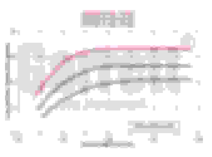
In practice, the operating characteristics of exhaust gas turbocharger turbines are described by maps showing the flow parameters plotted against the turbine pressure ratio. The turbine map shows the mass flow curves and the turbine efficiency for various speeds. To simplify the map, the mass flow curves, as well as the efficiency, can be shown by a mean curve
For a high overall turbocharger efficiency, the co-ordination of compressor and turbine wheel diameters is of vital importance. The position of the operating point on the compressor map determines the turbocharger speed. The turbine wheel diameter has to be such that the turbine efficiency is maximised in this operating range.
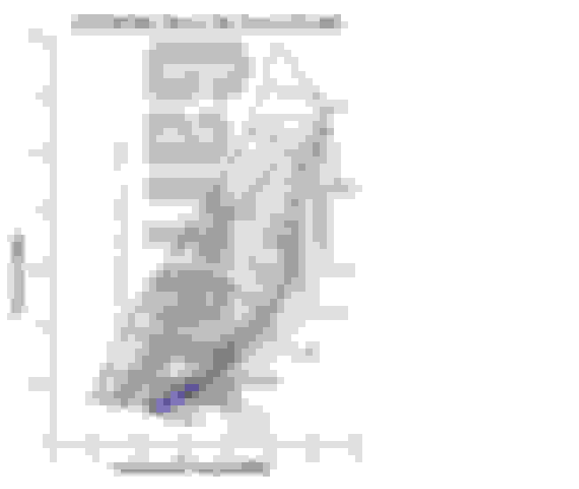
So taking from the description above and applying it to an example map for the GTx3076:
For the 1.06 housing it would seem the max. flow that would ever pass through that turbine would be 26(ish) lbs/min . And for most applications the actual flow will be less than this to achieve the required boost.
Now take the compressor map and we know the flow through a turbo13b is somewhere around 52lbs/min at a Pr of 2 . From that we can see shaft speed is around 112000rpm. We can see from looking at the B/W turbine map that shaft speeds of around there require less than full flow through the turbine so lets just say the turbine flows ..............25lbs/min .
So by my reckoning the wastegate in this situation needs to flow the remaining 27lbs/min.
Here's my take on it:
The higher the AR the higher the flow that the turbine tops out at, but just as important the more power the turbine can produce for the compressor at the high end.
For example a small turbine will restrict exhaust causing a higher pressure ratio at lower flows=>More power available to the compressor earlier. But it keeps that high pressure ratio as flow goes up and efficiency goes down (the remaining flow going out the WG) then after it peaks out on power there is no more to drive the compressor. If you went this route you should lower your boost at higher rpms, or you will just be creating backpressure. And that's without even looking at the compressor.
A large turbine on the other hand will take forever to develop back pressure. When it does start to build back pressure it will use the exhaust gasses efficiently and require relatively little WG. However it will only work well at high flows so it can develop the high pressure to drive itself. So no boost at low RPMs and great boost with low backpressure at high rpms.
Again this is all without looking at the compressor.
The mass flow rate is not even close to accurate with a rotary, divide the scale by .80 or multiply your mass flow by 1.2(don't want to confuse anyone) and it will get you in the ballpark. Because of the higher exhaust temperature the volumetric flow rate is higher for the same mass flow and its the volume that the turbine cares about.
It's a matter of preference. If you want a flat power band you want a low (relatively) AR turbine and then to drop boost pressure as you go up. If you want a dyno queen you go for a huge turbine and deal with horrible lag on the low end. There is no perfect answer, just a range of preference.
There is still more to it with sizing, but it's dinner time.
The mass flow rate is not even close to accurate with a rotary, divide the scale by .80 or multiply your mass flow by 1.2 and it will get you in the ballpark. Because of the higher exhaust temperature the volumetric flow rate is higher for the same mass flow and its the volume that the turbine cares about.
.
Great .... exactly the kind of info i was looking for ! Is the 1.2 figure a best guess ? Can we narrow it down some more ?
Educated guess. 1400f for piston 1700f for rotary convert to absolute and get a ratio. It can definitely be improved. Look for the rpm where the turbine runs out of flow at your target psi, above that you are just blowing wasting energy and making back pressure.
Lets look at two builds, one is a dyno queen, one is a DD. For the DQ I figure out how much air I want to flow at peak and then I match a turbine that flows AT LEAST that much air peak. The goal is to have all the energy from the exhaust going to drive the turbine and being just enough to drive the compressor. This keeps back pressure to a minimum. You can’t just look at the turbine map and figure out this point though, it takes some trial and error. At full flow the WG is almost closed, but at lower flows the WG is closed and there is not enough power to drive the compressor into full boost.
On the other hand I could build a DD. This time I don’t care about the turbine being large enough to flow all the air, I just care about it being large enough to drive my compressor at full boost. Again this is going to take some trial and error. At full flow the WG is pretty far open, and if not sized right can cause overboost. At lower flows the WG will keep the turbine full powered by modulating shut. Here if I go to big it spools late, or if I go to small the turbine can’t power the compressor at full boost (unlikely unless you have some weird custom build).
With the Garrett turbine map above the 1.06 seems ok for a DD build. At full flow it’s 26lbm/min or for a rotary say around 21lbm/min. That equates to being full powered around 6000rpm NA or 3000RPM at 2bar. It also begins to produce useable power at 4000rpm NA. So guessing from the map it will spool at around 3000-3500. And have more backpressure than larger turbines all the way up the range.
Remember AR only relates turbines or compressors of the same size. If you go bigger the AR required to flow the same amount will be smaller.
Hopefully someone with more real world experience can chime in. There are a lot of things that change when you go from paper to reality.
It's a general concept that assumes all else being equal. When you start talking about different turbine designs from different manufacturers then you have let go of preconceived notions and be more fluid to accepting actual results. Theory only goes so far, but the average book or forum worm that is a great reader but lacks real world experience tries to flog theory to point of splitting the RCH on a gnat i.e. apply more relevance to it than supported by reality.
I thought you said "multiply by 1.2" for a rotary ?
Yeah but it depends which way you are converting. 26/1.2 is about 22. I round down to 21, but it really doesn't matter its a rough thumbrule anyway. The point is that hotter exhaust gas has higher volume at the same mass. If the turbine can run 26lbm/min at cooler temps it will flow less at hotter temps.
Yeah but it depends which way you are converting. 26/1.2 is about 22. I round down to 21, but it really doesn't matter its a rough thumbrule anyway. The point is that hotter exhaust gas has higher volume at the same mass. If the turbine can run 26lbm/min at cooler temps it will flow less at hotter temps.
I must admit i thought you meant the other way around in your first post (26x1.2) and was confused by your logic .
So in my example above the wastegate has to flow a massive 31lbs/min .... 60% the total flow even with a 1.06 turbine!
Yeah but that's a small turbo with a large AR. Waste gate preferred has some advantages for a DD. Look at larger turbo exhaust maps.
I really want to stick to a low mount...... aiming for 400whp . But with what I have in mind I also wanted to minimise flow through the WG to about 45% of the total flow . If I went to a GT35 I would need to go to the 1.06 there as well to do any better and that is just too big for low mount.
That's why a 30 series Garrett is not considered a good match for a 2-rotor; turbine is considered under-sized for the compressor specific to the rotary requirement. Most people assume it's the compressor map. However, ithat turbine graph is based on the typical Garrett turbine design for that size wheel. Then you have companies like Precision etc. building alternate hybrid designs that can influence it to not only flow more mass through, but without a response loss too. The inducer/exducer diameters, blade shape, weight, etc. all play into the overall performance. Not always a cut and dry easy caculation or comparison against other designs.
That's why a 30 series Garrett is not considered a good match for a 2-rotor; turbine is considered under-sized for the compressor specific to the rotary requirement. Most people assume it's the compressor map. However, ithat turbine graph is based on the typical Garrett turbine design for that size wheel. Then you have companies like Precision etc. building alternate hybrid designs that can influence it to not only flow more mass through, but without a response loss too. The inducer/exducer diameters, blade shape, weight, etc. all play into the overall performance. Not always a cut and dry easy caculation or comparison against other designs.
Look at a GT30 1.06AR turbine map vs a GT35 0.82 ..... pretty much the same flow .
My point being .......... The GT35 is considered a good match and I would think that would include the smaller 0.82AR housing .
And my other point : It is clear to me that it's the total package (IE flow) of the turbine that really matters .... not so much the turbine diameter nor the AR by themselves.
Hi Kane ..........What is your take on how much mass flows through the same turbine on a rotary vs a piston engine?
I'm thinking the mass flow would be the same either way ...... to power up the turbine . Just the volume flow and therefore the velocity of the air (on the rotary) would be higher (due to the higher temp).
The mass flow through the engine stays the same. If the turbo map was scaled by volume it would all make sense. Instead it is scaled by mass because an exhaust temperature is assumed. Rotary break that assumption so you have to change the mass to make it fit. Not breaking thermodynamics, just fixing a bad assumption.
The mass flow through the engine stays the same. If the turbo map was scaled by volume it would all make sense. Instead it is scaled by mass because an exhaust temperature is assumed. Rotary break that assumption so you have to change the mass to make it fit. Not breaking thermodynamics, just fixing a bad assumption.
The Volume and the pressure difference drive the turbine. The reason the turbine map uses mass flow is because its a simple way of looking at the problem with available numbers, and because exhaust temperatures are assumed to be similar between piston engines.
Sorry if I got you confused. Been on dayquil so I don't promise complete clarity. I never meant that the actual mass flow changes through the engine, nor the max volumetric flow changes through the turbo. I just meant that at higher temperatures the mass flow through the turbo is lower because the volumetric flow stays the same.
 04-05-2015, 05:48 PM


 : It is clear to me that it's the total package (IE flow) of the turbine that really matters .... not so much the turbine diameter nor the AR by themselves.