Greddy install build-Adaptronic
#26
SARX Legend
iTrader: (46)
That's good, it should be short and direct. That TIAL QR is nice unit. My comment was about the one sold by a liar linked above as the placement of the fitting makes no sense to me since is faces towards the front bumper so the hose has to be routed in a "U" shape (well that's the way most who have it run it) back to the BOV or DV on the C6 pipe.
#27
SPOOLN8
iTrader: (1)
Join Date: Nov 2008
Location: Edmonton, Alberta, Canada
Posts: 2,225
Received 208 Likes
on
156 Posts
Good luck with build man, the pics reminds me of when I did mine solo off jack stands in my garage! Looks like you have the hard part completed in getting that turbo in there but you should have installed it with the actuator in place!
And Brett's right, I found the skinniest ratchet extension set I could at Princess Auto. Was the only way I could possibly get a socket on the DP to turbo connections without it slipping!
And Brett's right, I found the skinniest ratchet extension set I could at Princess Auto. Was the only way I could possibly get a socket on the DP to turbo connections without it slipping!
#28
Registered
Thread Starter
worked 3 straight days on this, and is finally together. i will post up some progress pics tomorrow.
now complete
-removed turbo again to install actuator (thanks Greddy instructions) this actually was terrible to have to start almost over again. really poor instructions. new ATP waste-gate actuator is too big 59mm, compared to 54.... won't fit. will tackle this in the spring maybe....
-charge piping/ bumper trimming etc.... used hairspray and cleaned all couplers with brake cleaner. previous owner never ran catch can and all the piping wake caked with oil.
-FMIC
-cleaned and painted all rusty dirty spots (canada eh... whatta gone doo)
-check valve for jet air vac line
-oil catch can
-removed rusty oil pan/ cleaned/ sanded and painted- drilled hole for return line
-lost the upper strut nuts.... trip to dealership to get 3 of these
left to do.....
-install oil pan with new high temp sealant
-heat wrap return line
-fabricate NASA style heat shield for down pipe area
-lotek gauge cluster
-wiring of gauges
-install and find location for fuel pressure sensor
-install and find location for coolant temp sensor
-wiring of AEM O2 wideband to adaptronic ssi box
-plug in ECU adaptronic
-obtain base map and install
keep the positive comments coming.....
Last edited by yurcivicsux; 09-22-2015 at 12:28 PM.
#29
Registered
Thread Starter
Good luck with build man, the pics reminds me of when I did mine solo off jack stands in my garage! Looks like you have the hard part completed in getting that turbo in there but you should have installed it with the actuator in place!
And Brett's right, I found the skinniest ratchet extension set I could at Princess Auto. Was the only way I could possibly get a socket on the DP to turbo connections without it slipping!
And Brett's right, I found the skinniest ratchet extension set I could at Princess Auto. Was the only way I could possibly get a socket on the DP to turbo connections without it slipping!
#30
Registered
Thread Starter
That's good, it should be short and direct. That TIAL QR is nice unit. My comment was about the one sold by a liar linked above as the placement of the fitting makes no sense to me since is faces towards the front bumper so the hose has to be routed in a "U" shape (well that's the way most who have it run it) back to the BOV or DV on the C6 pipe.
Last edited by yurcivicsux; 09-22-2015 at 12:28 PM.
#31
Registered
Thread Starter
#32
SPOOLN8
iTrader: (1)
Join Date: Nov 2008
Location: Edmonton, Alberta, Canada
Posts: 2,225
Received 208 Likes
on
156 Posts

An yeah BOV signal line goes to Vfad nipple just behind TB... The way you are describing the vacuum hoses sounds right but I threw some pics in Brettus' thread years ago that should help you out.
Otherwise; good stuff dude!
#33
Registered
Thread Starter
i think i got the yellow and white mixed up... will switch this around tomorrow. also surprisingly i don't have a lot of rust considering it's a Mazda, oil sprayed and only summer driven for the last 4 years. you still get a bit here and there in some areas under the battery tray....all cleaned up now.
funny a buddy of mine asked who has a turbo 8... my response was "a guys in SK with a yellow one" don't know of anyone else yet.... at least they aren't coming to the meet ups around Toronto...
where is this vac line at the back of the throttle....?? my eyes start to get sore from all the reading on this forum.... maybe you can link a quick thread or pic?
easily half the work involved for the build..... keeping up with the posts here.... part of the fun i guess....although sometimes too many conflicting opinions and ways to do things can be confusing...
#34
Registered
Thread Starter
#35
SPOOLN8
iTrader: (1)
Join Date: Nov 2008
Location: Edmonton, Alberta, Canada
Posts: 2,225
Received 208 Likes
on
156 Posts
Yeah I actually mixed mine up at first and I was driving around with it like that for a while but that was just on a base tune and I wasn't hitting any boost before I noticed; didn't hurt anything.
I don't have a picture because I'm way up north for work right now, but right behind the TB on the driver side there is a nipple (part of the manifold) that is part of the stock air intake VFAD system,
You would of had to remove a hose off it to remove the stock intake, it is pointing straight down towards the ground. Directly behind the driver side bottom corner of the TB
#36
SPOOLN8
iTrader: (1)
Join Date: Nov 2008
Location: Edmonton, Alberta, Canada
Posts: 2,225
Received 208 Likes
on
156 Posts
https://www.google.ca/search?q=rx8+V...q4tcpd2QK9M%3A
VFAD nipple picture ^^
It's like directly behind where the coolant hoses go into the TB.
VFAD nipple picture ^^
It's like directly behind where the coolant hoses go into the TB.
Last edited by RotaryMachineRx; 09-20-2015 at 09:01 PM.
#37
Registered
Thread Starter
https://www.google.ca/search?q=rx8+V...q4tcpd2QK9M%3A
VFAD nipple picture ^^
It's like directly behind where the coolant hoses go into the TB.
VFAD nipple picture ^^
It's like directly behind where the coolant hoses go into the TB.
okay perfect run a 3/16 ID hose from that to the blow off valve. thanks... really appreciated. I was assuming this was correct....
#38
Registered
Thread Starter
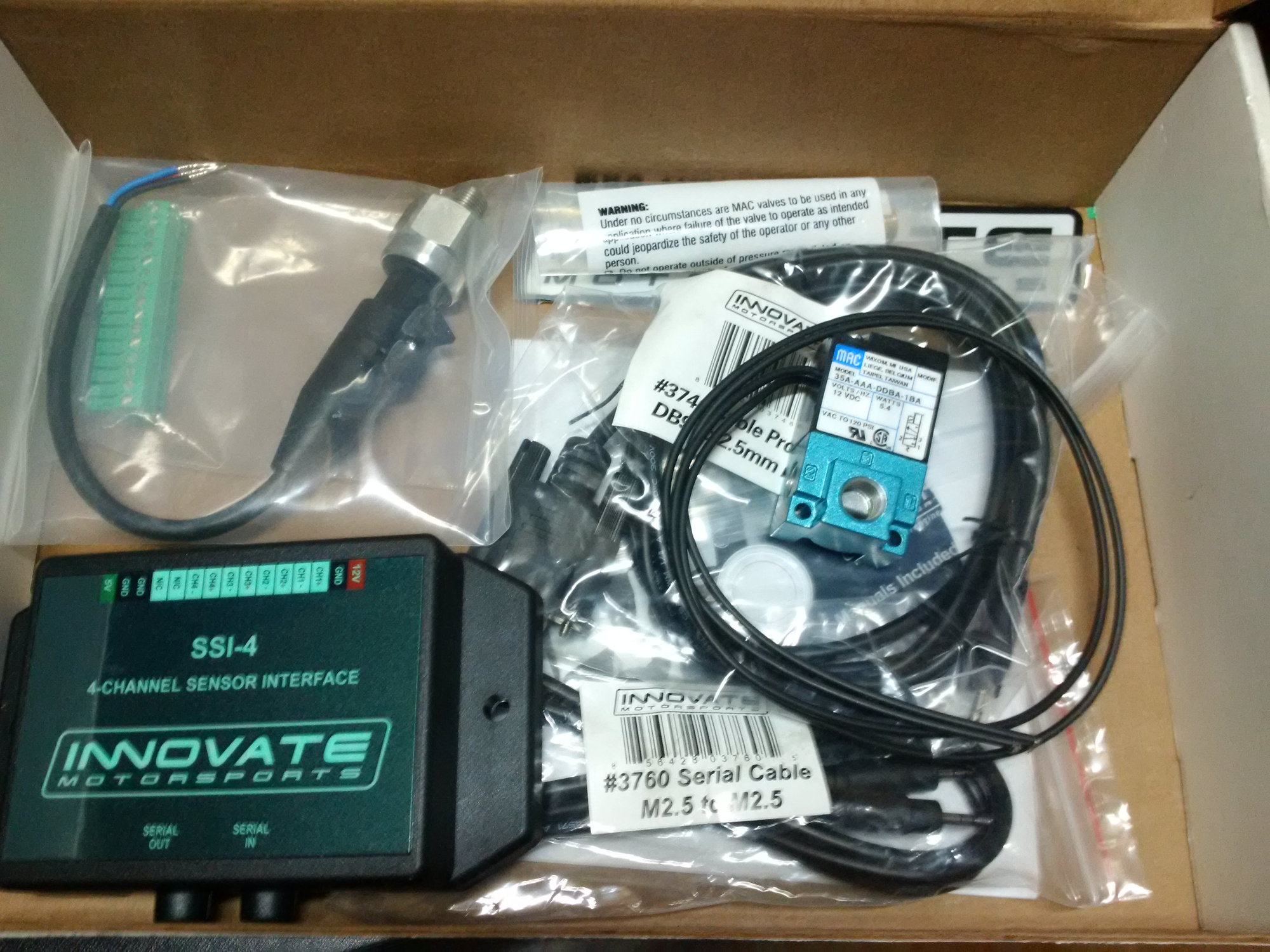
SSI box, electronic boost controller, fuel pressure sensor for SSI box. ECU will see low fuel pressure and govern engine. (engine protect mode). this is good insurance until I fix the float on my fuel pump
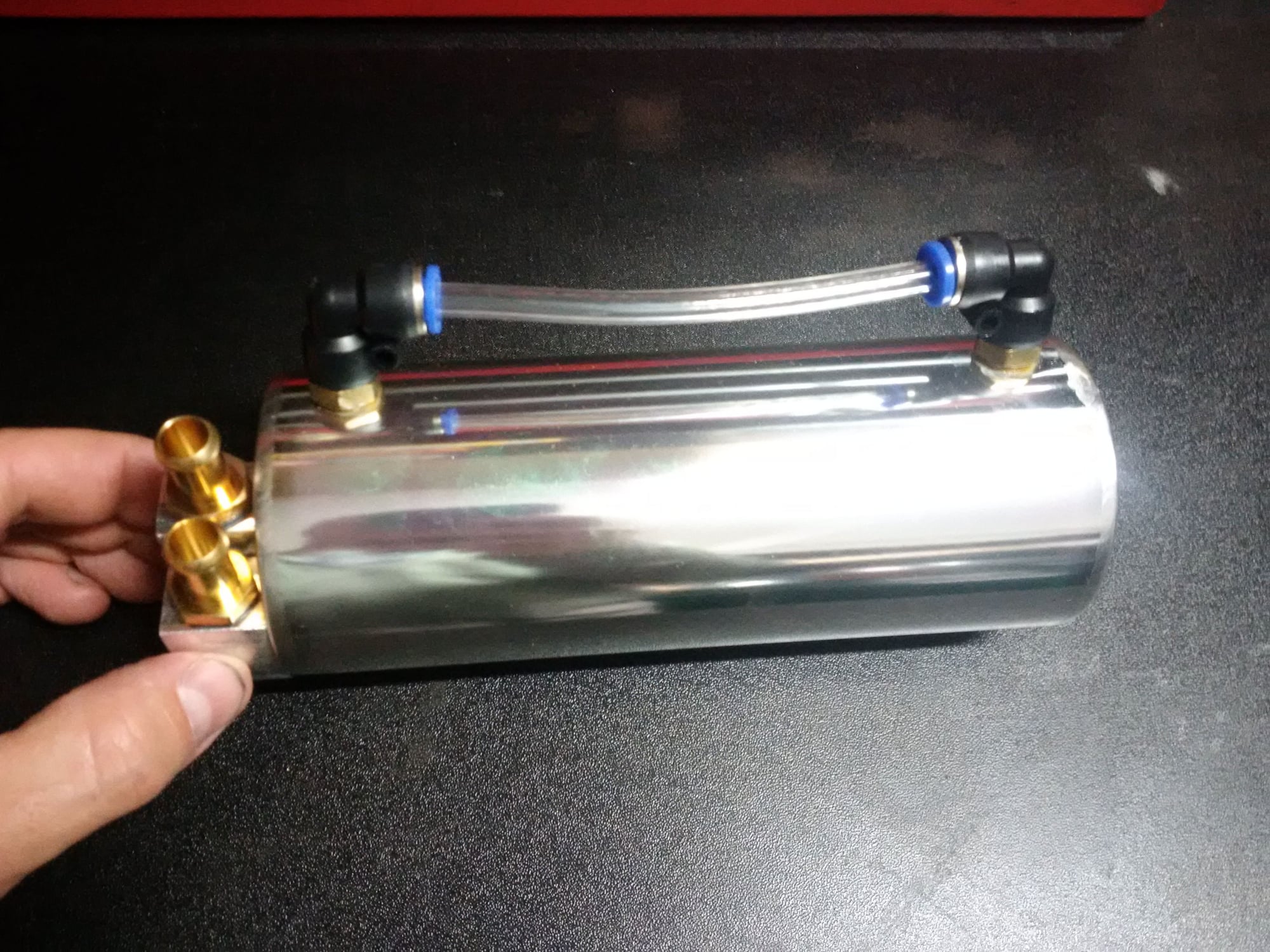
generic catch can.... perfect for $58 shipped. whoo hoo
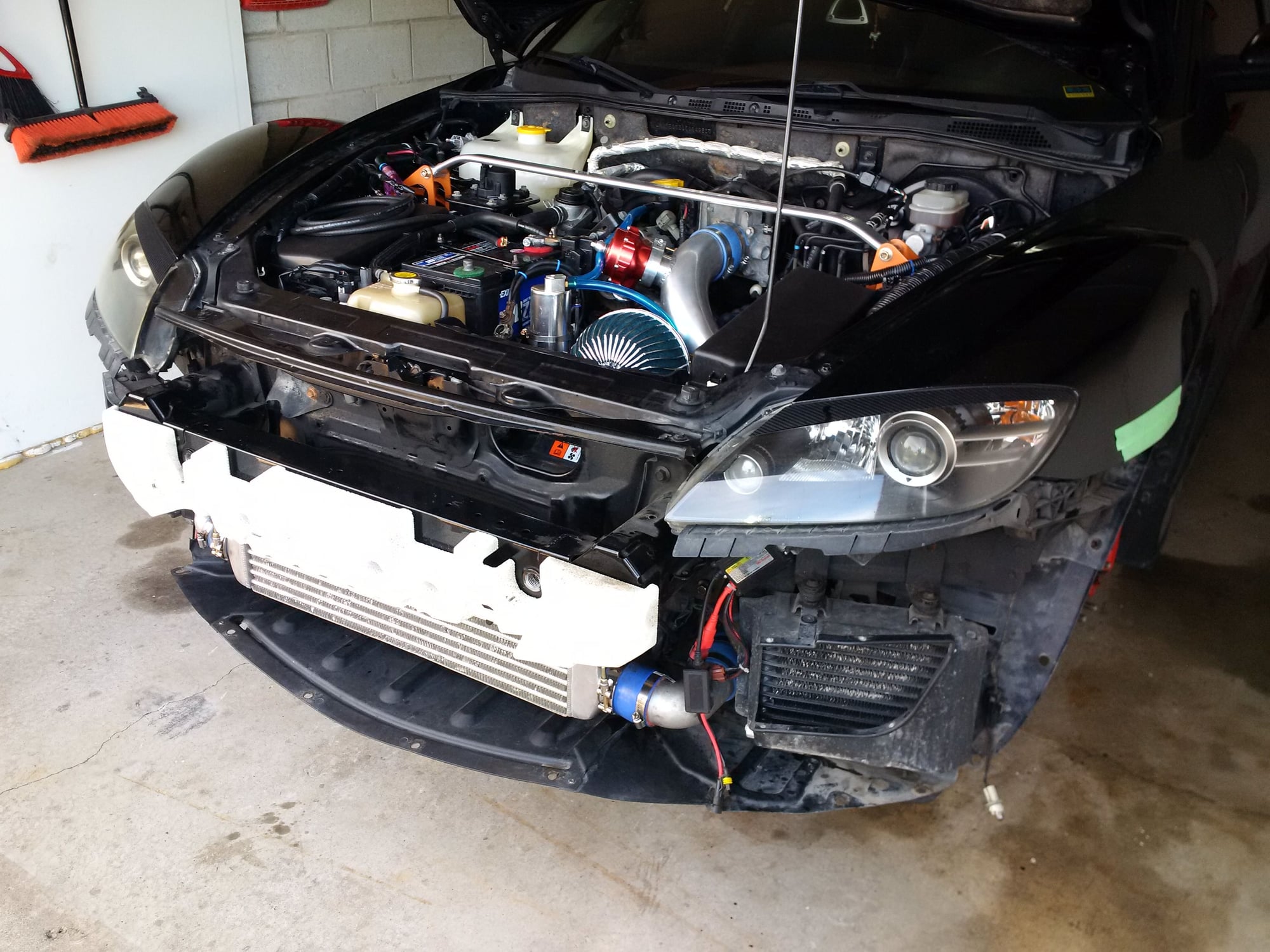
all installed, oil pan, gauges, and ECU left
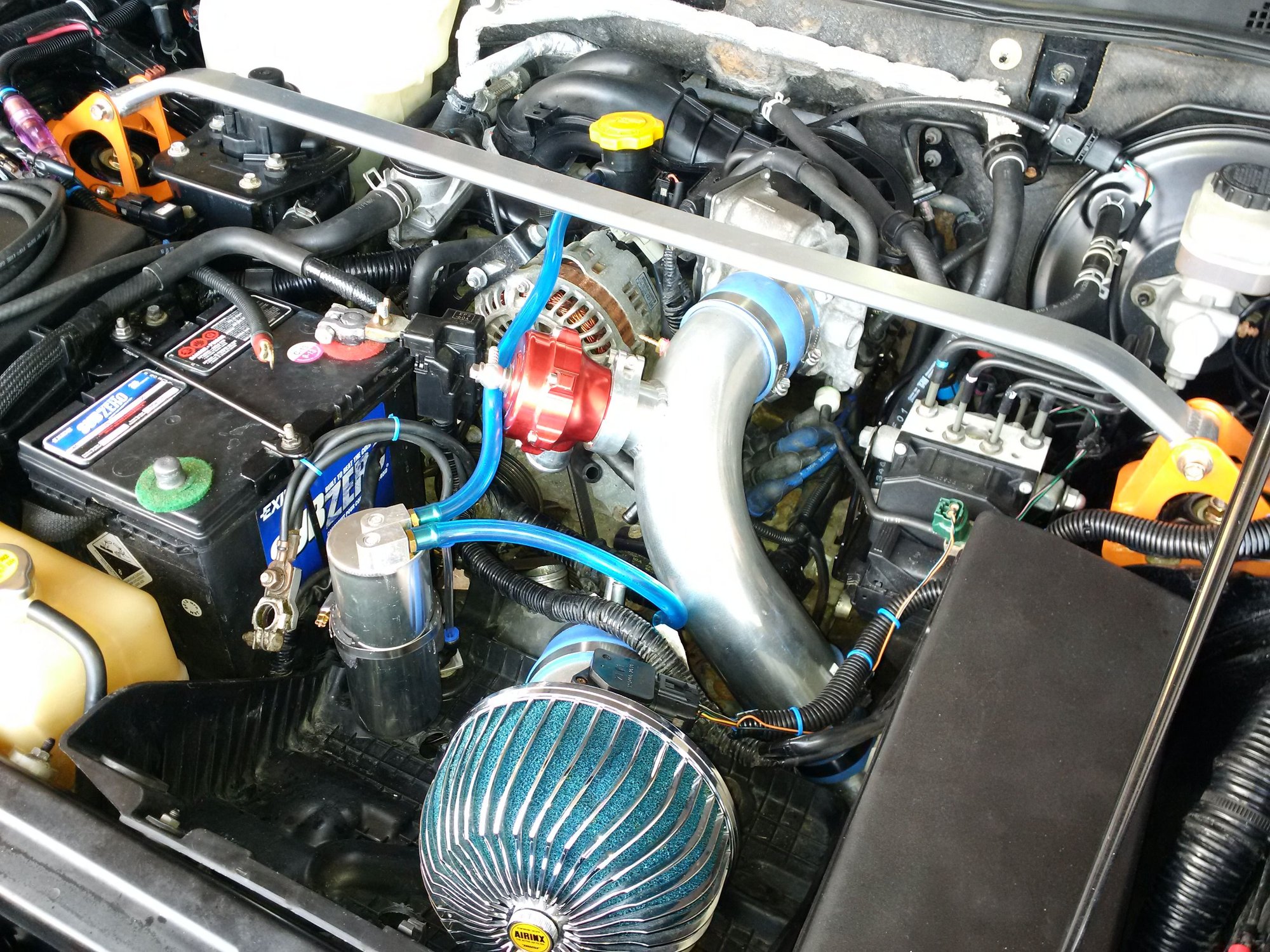
eventually will run this out to front bumper. (spring project)
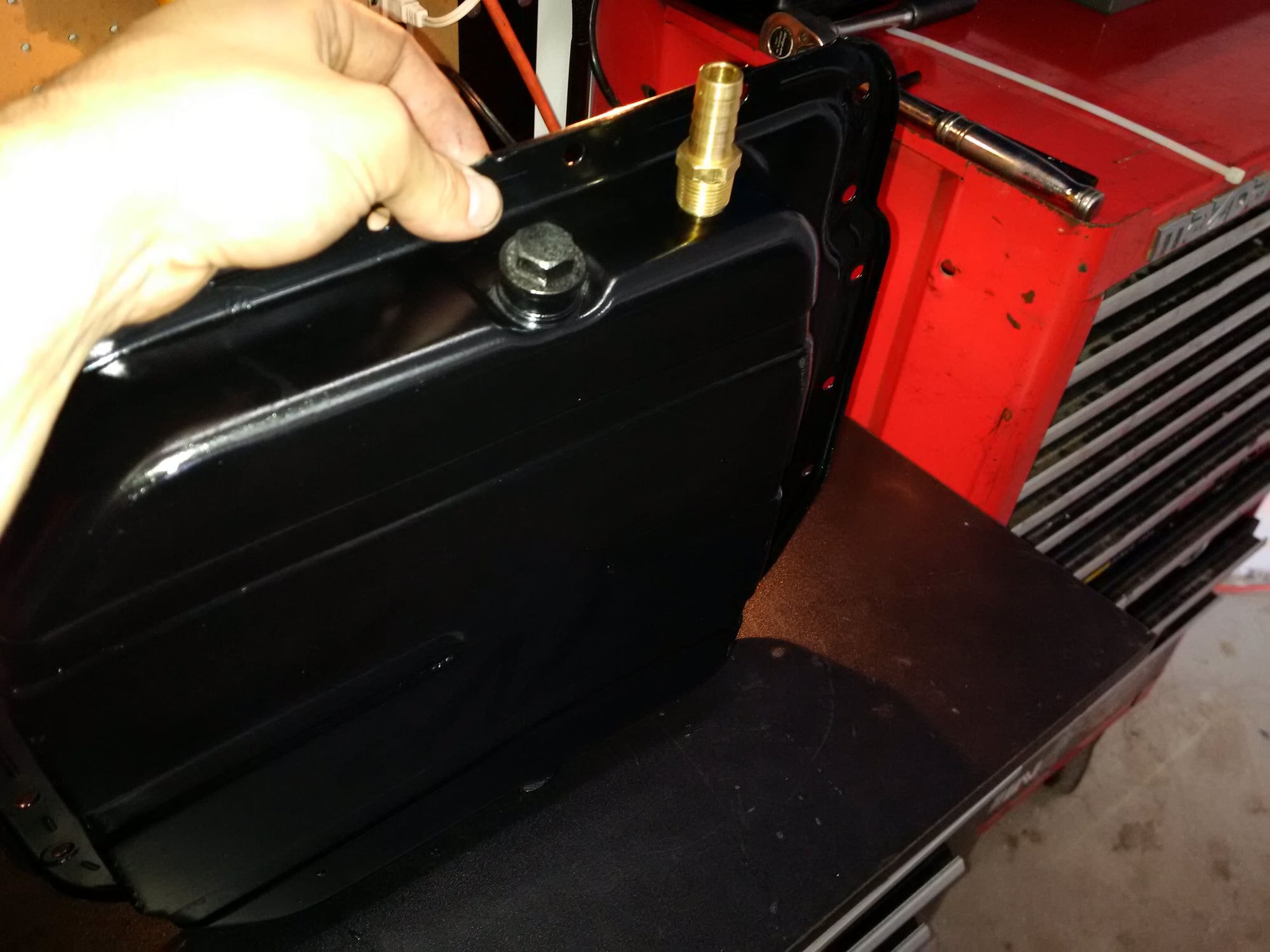
oil pan all cleaned up and painted. mounting barb thread tonight

one way check valve for jet air line
some more pictures.
#40
Registered
Thread Starter
concerned about how the adptronic ECU sits open in the engine bay. I know a few guys are using these is moister a concern? just thinking about what would happen if it got wet for whatever reason. as you know the harness is exposed.
will do some searching........
will do some searching........
#41
Registered
Thread Starter
I know I'm also concerned might put some glue or hairspray inside the fitting or use fuel line clamps instead of gear clamps. the main one is where it connects to the LIM apparently there is no barb there and I can't reach it. maybe I will get lucky as it's an 2005 the line might be 'stuck' on pretty good as rubber lines sometimes get.
#44
SPOOLN8
iTrader: (1)
Join Date: Nov 2008
Location: Edmonton, Alberta, Canada
Posts: 2,225
Received 208 Likes
on
156 Posts
I know I'm also concerned might put some glue or hairspray inside the fitting or use fuel line clamps instead of gear clamps. the main one is where it connects to the LIM apparently there is no barb there and I can't reach it. maybe I will get lucky as it's an 2005 the line might be 'stuck' on pretty good as rubber lines sometimes get.
As for the connections on the jet air to the LIM.... I didn't put any extra clamps on mine either and I've been going 5 years strong without an issue (knock on wood).
#45
Registered
Thread Starter
I don't believe the check valve is even required if you are connecting it to the C6 charge pipe like that (flow will always be going from charge pipe to LIM no matter what as LIM will have higher vacuum and lower boost than charge pipe at all times).... I don't have one at least and it would eliminate 2 potential leaks, but the worm gear clamps should be plenty to hold that on and prevent any leaks.
As for the connections on the jet air to the LIM.... I didn't put any extra clamps on mine either and I've been going 5 years strong without an issue (knock on wood).
As for the connections on the jet air to the LIM.... I didn't put any extra clamps on mine either and I've been going 5 years strong without an issue (knock on wood).
#46
SARX Legend
iTrader: (46)
Yeah if you use quality vacuum hose (and not just any silicone hose advertised as vacuum hose) it should not come off but I still use zip ties anyway. And yeah I have my jet air to the intake and nothing on the C6 pipe.
#47
Registered
Thread Starter
[/QUOTE]And yeah I have my jet air to the intake and nothing on the C6 pipe.[/QUOTE]
interesting I would have thought for sure you would need a check valve as in theory it makes sense.
interesting I would have thought for sure you would need a check valve as in theory it makes sense.
#49
SPOOLN8
iTrader: (1)
Join Date: Nov 2008
Location: Edmonton, Alberta, Canada
Posts: 2,225
Received 208 Likes
on
156 Posts
interesting I would have thought for sure you would need a check valve as in theory it makes sense.[/QUOTE]
Yeah the check valve is needed if you route it back to the intake, because then when the LIM has boost the intake doesn't meaning boost leak. But if it is connected to the charge pipe it is not required as the charge pipe ALWAYS has a greater pressure than the LIM, in vacuum and boost so there is never reverse flow through the jet air hose. As you stated though.... your check valve isnt hurting anything whatsoever as long as you put it in so flow is going towards the LIM!
Last edited by RotaryMachineRx; 09-21-2015 at 04:09 PM.
#50
Lucky #33
iTrader: (4)
On another note, let me know how that SSI works out for you. I plan on doing that same mod myself some day.


