When you click on links to various merchants on this site and make a purchase, this can result in this site earning a commission. Affiliate programs and affiliations include, but are not limited to, the eBay Partner Network.
I’m writing this build thread w/ the intention to make a positive contribution to the community from which I’ve learned so much, pro & con, about our cars and FI over more than a decade. Hope the challenges…, resolutions…detailed in my build thread will add to the reservoir of useful information and be of assistance to others who may choose to undertake the same. Some quick data points:
Forum join date: 1Q06
Initially investigated FI: 3Q07 – 1Q10. Backed away b/c I was uncomfortable w/ hardware, software, tuning options.
~1Q17 (car long paid off, & warranty expired, ;-) Had a revived interest in potentially boosting my 8 and began investigating FI again. Pleasantly found a more mature aftermarket offering IMO improved hardware, S/W, and tuning options.
Many thanks to this forum, it’s admins., contributors, those who’ve posted build threads, & all who’ve been committed to driving theory, experiential or substantiated knowledge, and improvements particularly w/in the Major Horsepower environment. Below are a few, but by no means an exhaustive list:
Brettus
Mazda Maniac
Rotarygod
Kane
RX-Tuner
Gregs
Charles Hill
Mysql101
RotaryMachineRX
tdiddy
ChrisRX8PR
Strokercharged95gt
JimmyBlack
TeamRX8
and more…
Most valued build thought: “At some point, everything's gonna go south on you... everything's going to go … you can either accept that, or you can get to work. That's all it is. You just begin. You do the math. You solve one problem... and you solve the next one... and then the next. And If you solve enough problems ... you'll have the reward of driving a rad 8. ;-) Adapted from Mark Watney, “The Martian”
My Approach:
Read, read, read, avoid mistakes, and incorporate lessons learned by others.
Plan. Work systemically. Installation sequence is important.
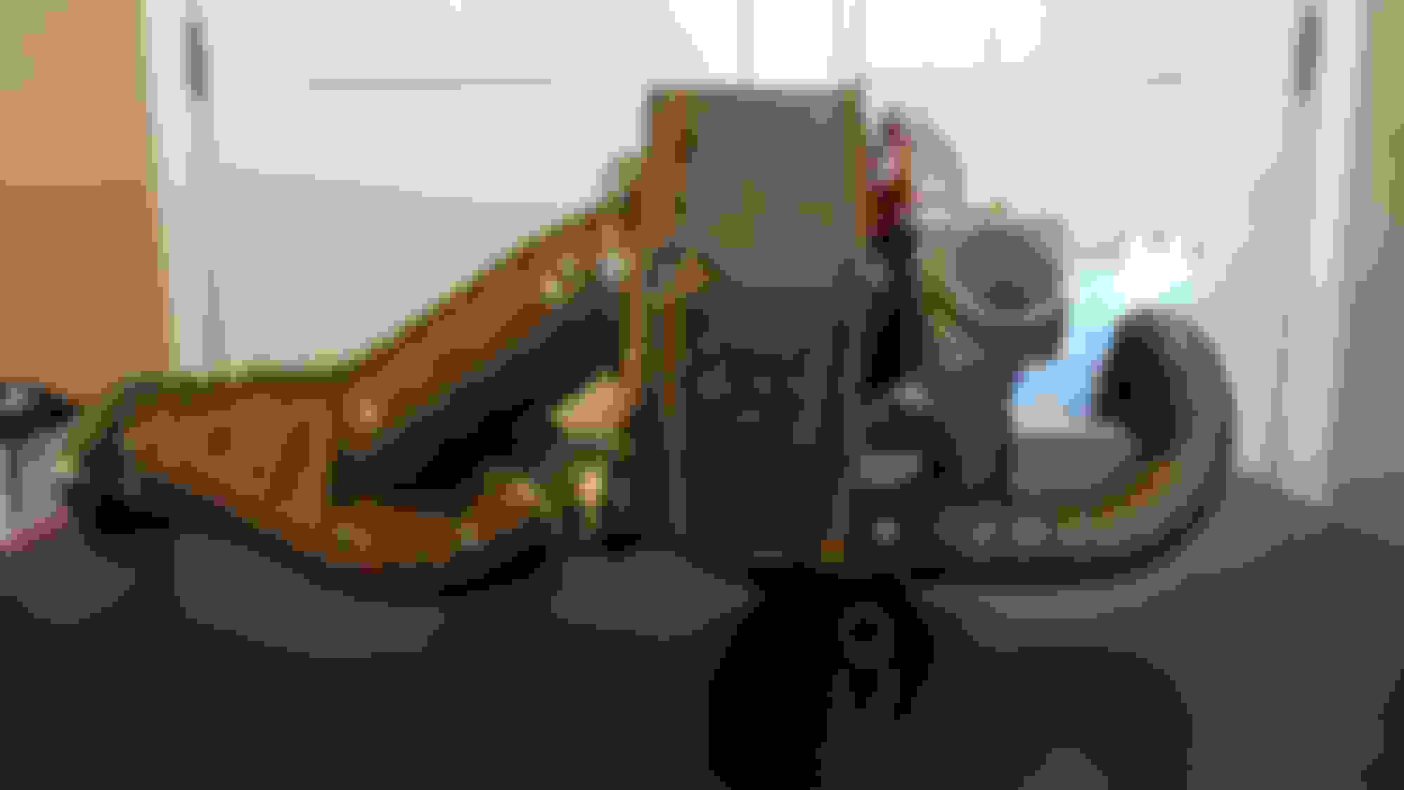
Let’s get at it… So, first up…prep-work (some shown above): - dry ran assembly of the kit - heat wrapped manifold, & downpipe - 2nd dry run fit after wrapping. - drilled & tapped intake & charge tubes - installed intake and charge hose fittings
First matter of install business was to prepare my 8 for install, and tackle fuel system work: - lifted my 8, and drained the oil - removed under cover, air box, TB, & UIM - battery h/b relocated to trunk a while back - installed new fuel injectors (Sec & P2) and swapped existing yellows into P1 - installed fuel pressure sender - pressure tested fuel system. (Greg, Thx for pointing me to this process!)
- unfortunately, the pressure test revealed a fuel leak. - removed, inspected, greased, & re-inserted fuel injectors. (Brett, Thx for the best practice assist) - Retested & confirmed fuel leak resolved.
While working top-side I continued w/ gauge senders, AP hardware delete and oil filter relocation. - Installed water, oil & fuel press senders - removed air pump hardware - plumbed vac hoses to OMP, & jet air (while UIM was off) - removed deleted AP vac hose, & plugged solenoid - installed oil filter relocation kit head mount - started playing w/ ideas for catch can and remote oil filter mount
Next transitioned to working underside… - removed ~200 F OEM and installed 175F oil cooler thermostats - removed the three structural braces - removed OEM oil pan - installed new high capacity oil pan - discovered that the turbo oil drain port on the pan was obstructed by the trans bell housing - ground trans bell housing to create clearance to terminate turbo oil drain - installed new spark plugs
Next up… - supported engine via floor jack - removed OEM motor mounts - removed midpipe - removed OEM manifold - installed add’l heat insulation over trans tunnel, and along passenger footwell.
Now time for the heavy lifting so to speak… - constructed & terminated oil feed to turbo - discovered access was too tight to fit turbo into space.
- Resolution: hammered passenger wheel well area to enlarge access to slide the turbo into the space - lifted turbo into mounting space - attempted to install manifold, but discovered studs are too long to seat mani (studs were making contact w/ the backside of the runners).
- Resolution: ground lower left & middle mounting studs to fit turbo mani - installed turbo (this task was a beeaasst!)
NOTE: Critical best practice here: support engine under oil pan (w/wood to distribute weight). ENSURE floor jack is perpendicular to engine/trans line (see previous pic). Throughout the mani, turbo, DP, & WG install; use the jack to lift, lower, and move the engine laterally to enlarge the working space as needed. (Scott, Thx for the huge best practice assist!)
- Also kudos to Scott on kit design, and thanks to my dry run install of mani-turbo-DP-WG out of the car…once the mani & turbo were mounted; the mani-DP-WG "triangle" junctions installed & mated-up easily...even for a novice. ;-) - installed DP - installed WG
Clean install so far, and good pics. Nice to see one of these kits up close - quality looks good.
That trick with greasing the injector seals is a killer!
Having completed the mani / turbo / DP / WG I began moving toward the FMIC. - installed driver & passenger motor mounts - installed turbo oil drain - removed front bumper - began laying out FMIC mounting - began considering EBC WG controller mount locations and hose layout to WG.
FMIC mounting… - mounted IC w/ the RX8P bracket - attempted to re-install the crash bar, but couldn’t… - discovered two issues w/ the RX8P IC mount: 1. the IC position obstructed remounting of the crash bar. 2. the RX8P bracket obstructed the CAI access into the engine bay. - Resolution: designed my own IC bracket, which resolved both issues. - cut off the bottom Ż of the crash bar to increase direct airflow to more bars of the IC. (adopted idea from Discotech’s thread) - re-mounted crash bar w/ IC mount
Installing charge and CAI sections… - installed compressor inlet section - installed charge sections:
,,,comp. out –> FMIC,
,,,FMIC --> eng bay,
,,,eng bay --> TB
- discovered that the last charge section (pre-TB) is shorter than ideal. - Resolution...ordered 6” long, 45-degree coupler. Worked perfectly.
- Plumbed vac OMP & jet air vac hoses to intake - installed intake section w/ air straightener - Installed CAI
Continuing work w/in the engine bay… - designed new mounts for: ,,,oil filter, ,,,catch can (newly installed), ,,,heat sink, ,,,baro sensor
- installed oil filter relocation kit & catch can mount w/ oil drip catch - constructed & installed oil filter lines - constructed & installed turbo filtered oil feed line - plumbed vac hoses to the oil filler via catch can - installed BOV & recirculation hose
What NOT to do: So, I installed the remote oil filter mount / turbo feed / catch can set-up. On first start it leaked, Took It all apart "thread sealed" everything, and re-assembled. Started car again and realized that it was the 1/4 NPT port not being used leaking. It wasn't critical to my design, never tightened it. -->
Continued w/ installation of the WG control module & pressure test of the system: - designed simple mount and mounted the EBC WG control module - pressure tested system. (Brett, Thx for the assist w/best practice for set-up)
- System pressure test set-up and results:
- set-up: Cap @ CAI, Cap w/ air fitting at TB coupling. Oil filler, J-Air, & OMC intake nipples capped.
Test 1: ~ 7 PSI air leak at BOV. Resolution: Loose hose clamp, and not completely seated BOV nose flange.
Test 2: ~ 10 PSI black expansion cap blew off. Trip to Lowes ...replaced with hard PVC coupler w/ cap.
Test 3: @ 20 PSI, leak down rate is ~ 3 psi over 60 secs.
W/ system successfully pressure tested…finished running & plumbing vac & charge hoses… - removed pressure tester, and reinstalled CAI & TB couplers. - normalized jet air & OMP (w/ chk valves), and oil filler vac hoses. - ran UIM charge / vacuum hoses to BOV - fitted tee @ UIM rear port (...to support EBC & AEM vac/boost source) - ran charge section hoses to WG and EBC control module
Edit: I rerouted the WG control lines. They now route over the trans then down to the WG. Much better routing for their protection as shown in last pic.
oil leak, which turned out to be multiple sources: filter reloc head mount & oil pan
***Note: installing new hardware is exhilarating. Removing new hardware is NOT.
- began diagnosis and resolution of exhaust mani leak
- removed recirc, comp inlet, midpipe, DP, & detached turbo from mani. - removed oil drain and moved turbo forward in the space
- cleaned garage before proceeding... out of frustration and b/c it was a mess.
Delivering the package… - labored long literally to remove mani... (challenging.) - finally, the baby is DELIVERED! Turbo & mani out.
**Note: First time install and removal was a BEAST!
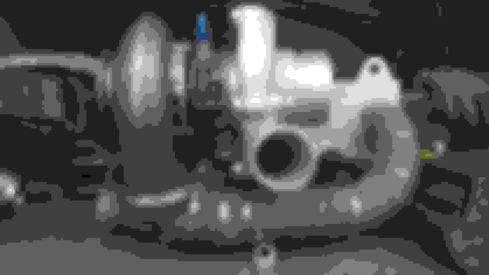
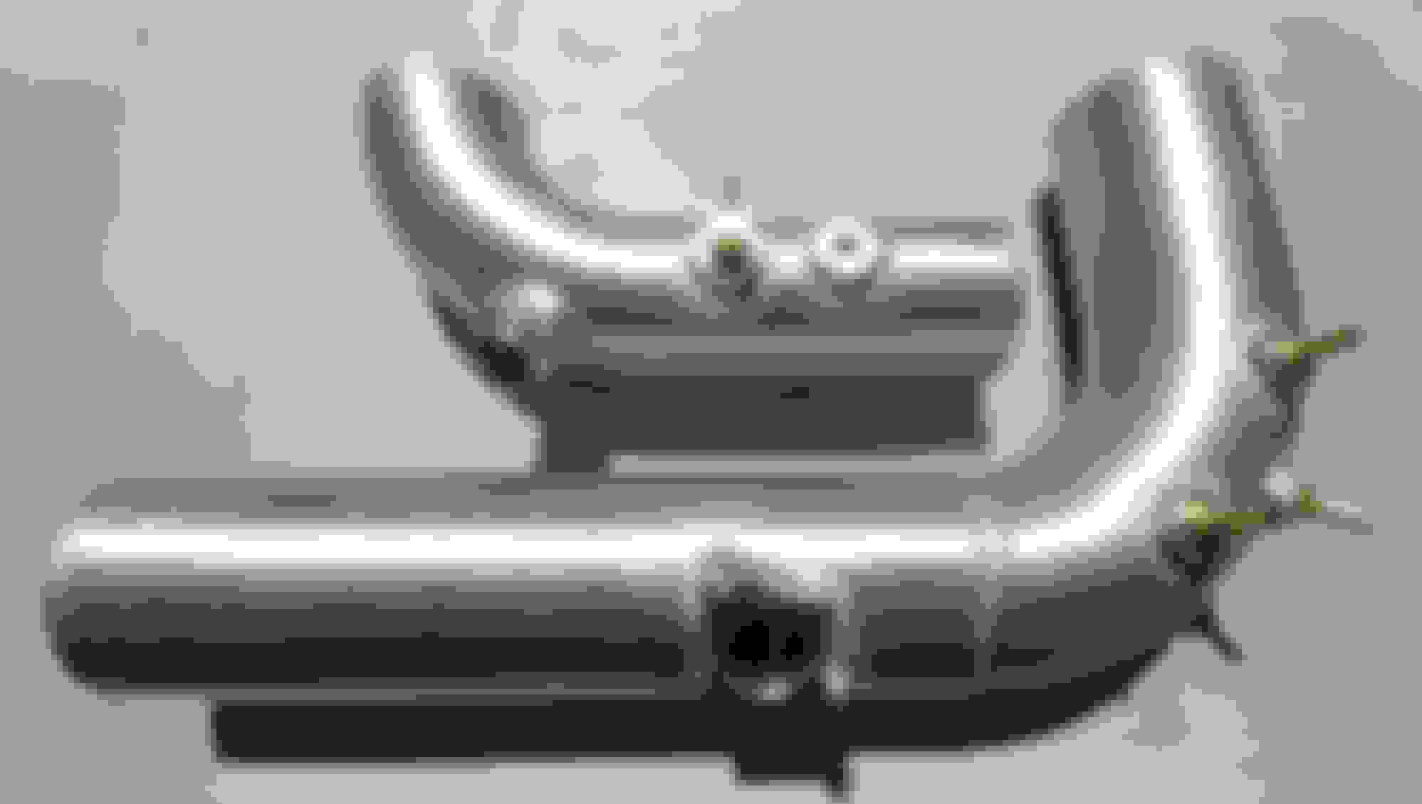
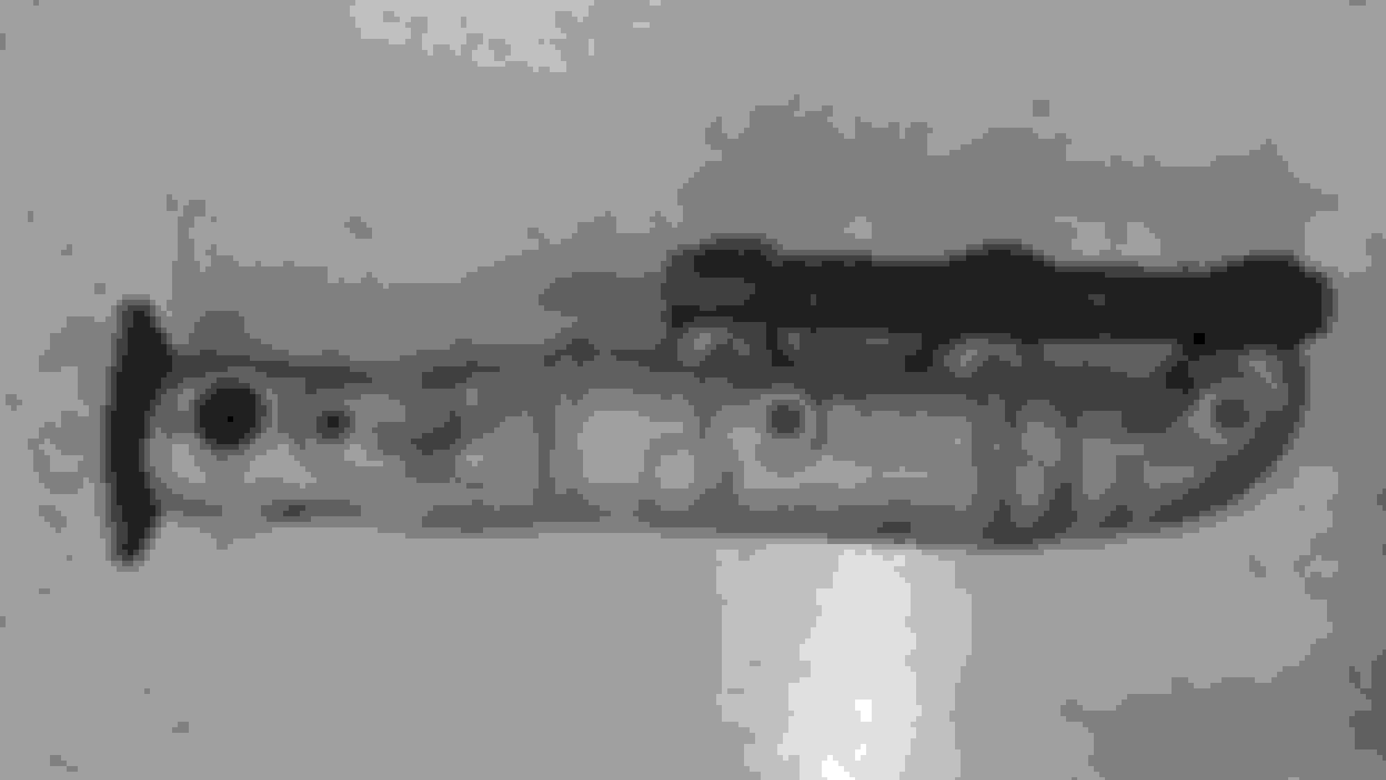
- discovered the exhaust leak was a result of the studs still being too long to accommodate the mani runner tight radius bends! The studs were making contact w/ the runners, prohibiting the mani from seating fully, and creating likely ~ 1-2 mm gap along entire bottom of mani to engine. Smh
though I ground the studs initially... I failed to confirm them short enough.
See pics: The red & black marks are the lengths of the bottom left & middle studs respectively. You can see the mani backplate to runner distance is too short to accommodate the stud length.
- So, it’s the grinder again for the offending studs and confirmed them short enough for the manifold to fully seat.
QA little mani work… - I took the opportunity having removed the mani to address another *potentially* contributing issue I identified early on but chose to initially ignore. IMO the kit is well designed from a flow and quality of fabrication perspective.
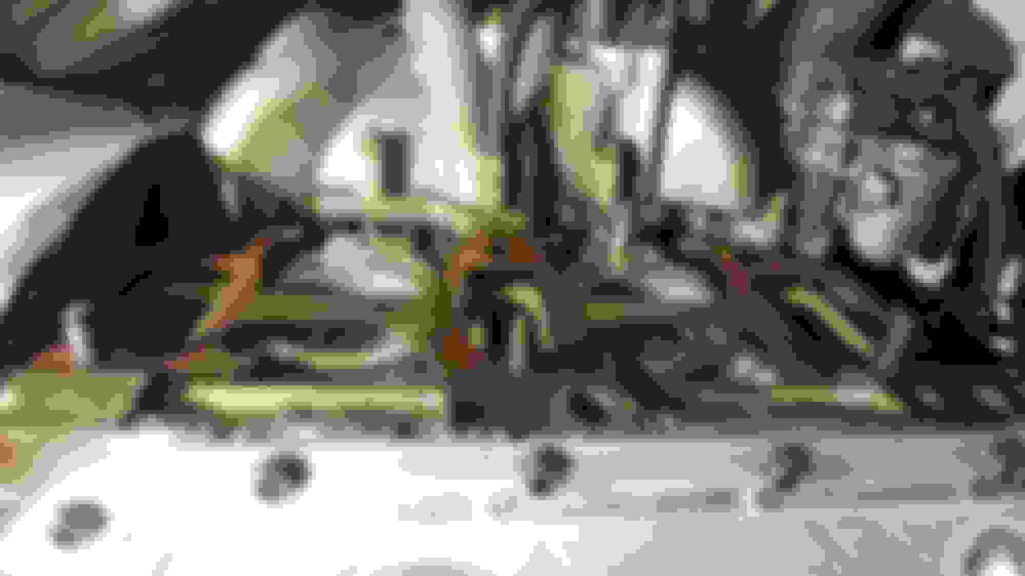
- However, I found the distance between the mani middle runner and turbine mount too tight for my install comfort. With the turbine mounted to mani, my turbo (6266) compressor clocking range was limited thereby increasing the difficulty of simultaneously achieving a proper turbine seal and comp. outlet facing out into the passenger wheel well…all in a tight work space. **Note: I’m not saying that installation as is was not possible, simply that it made the task more difficult.
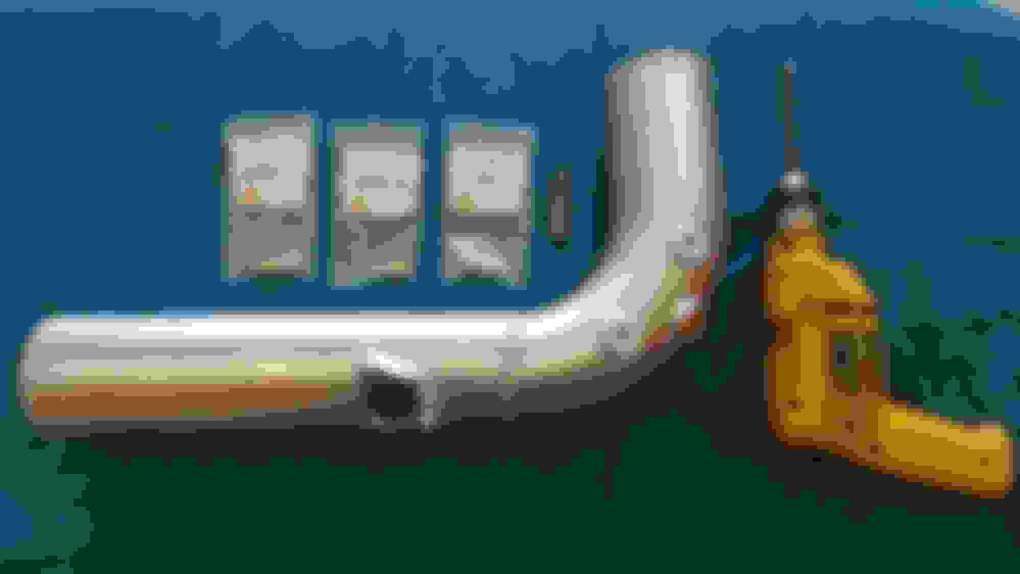
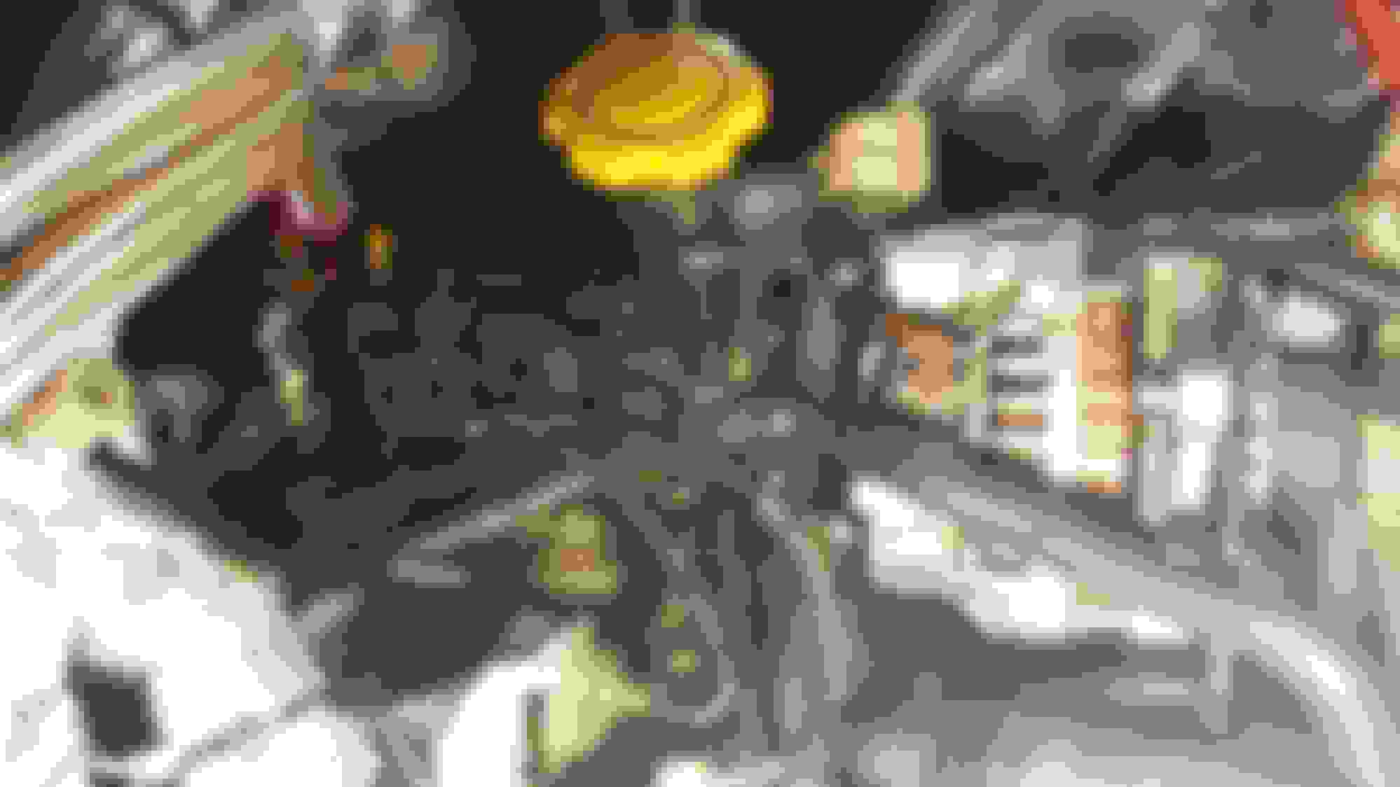
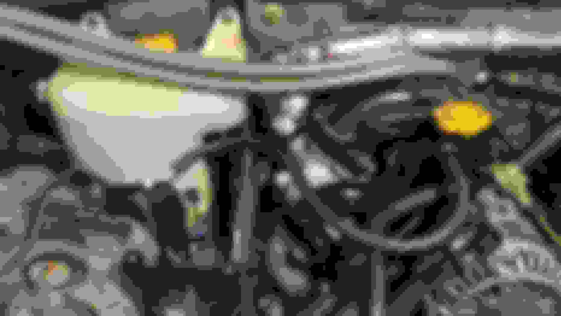
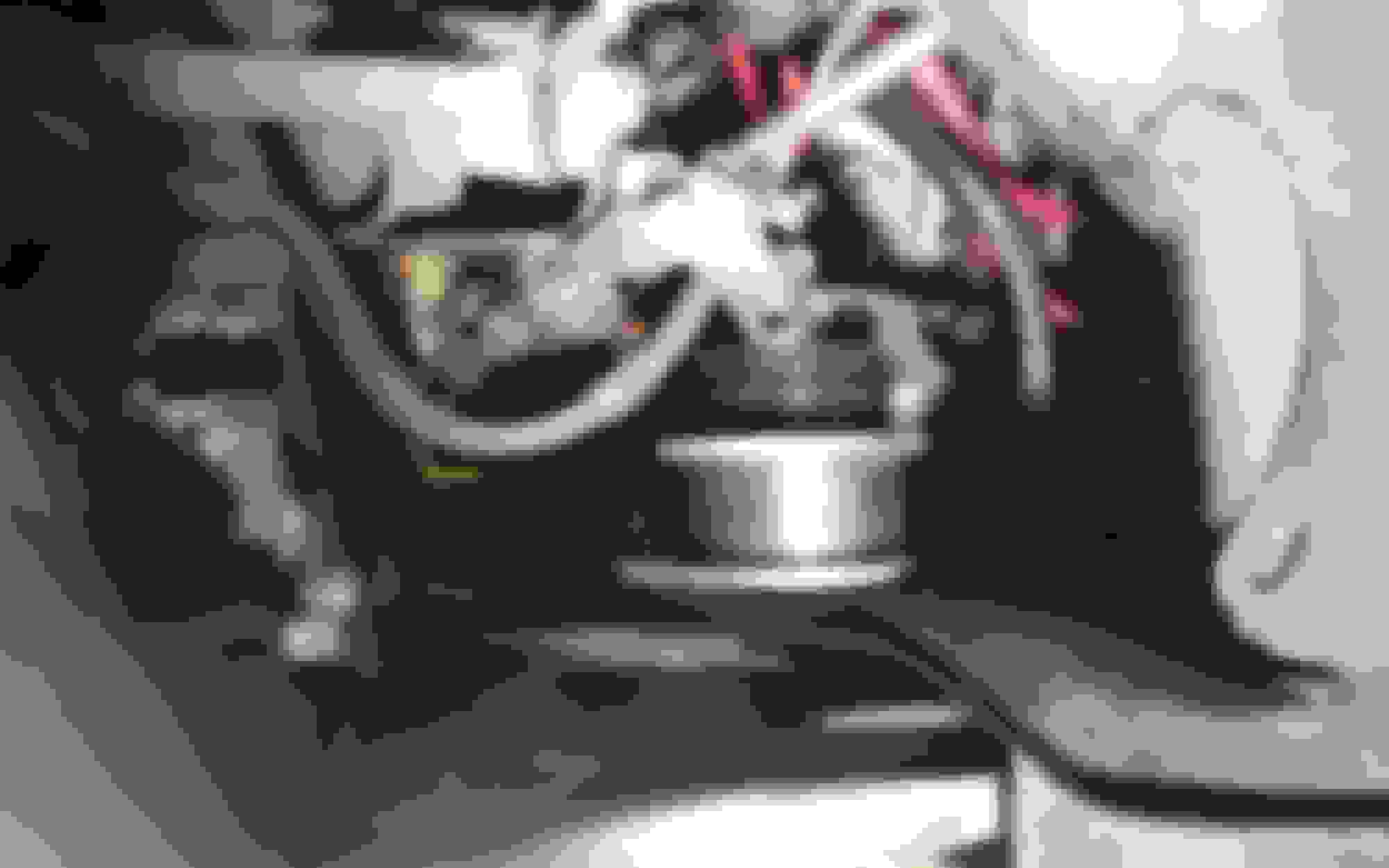
- So I sourced a local fabricator to "work" the middle runner over (away from the turbine mount) creating ~ 15-20 deg. additional clocking, which resulted in a much easier install.See the pre & post comp outlet best clocking position pics below.
.
.
. Note: Bestcompressor outlet clocking position before reworking ex-mani.
So, moved on to addressing the oil pan leak. - removed oil pan, cleaned sealant, and re-installed. - after allowing oil pan sealant to cure refilled her w/oil - started her again... - better…, but still had an exhaust leak!! - …and small, but present oil leak as well. - vid: 2nd engine start: (May have to cut & paste into browser):
"At some point, everything's gonna go south on you... everything's going to go … you can either accept that, or you can get to work. That's all it is. You just begin. You do the math. You solve one problem... and you solve the next one... and then the next. And If you solve enough problems, you get to ...” drive a rad 8. - Excerpted from Watney, “The Martian”
- So, addressing the exhaust leak first…this time used soapy water to t-shoot & confirm source(s) of leak. (Travis – Thx for the best practice assist.) - Yep,… exhaust leak still at mani B-L & B-M studs. “ - re-drained oil and started disassembly... BOV, comp inlet, motor mounts, midpipe, WG, DP, turbo, etc.
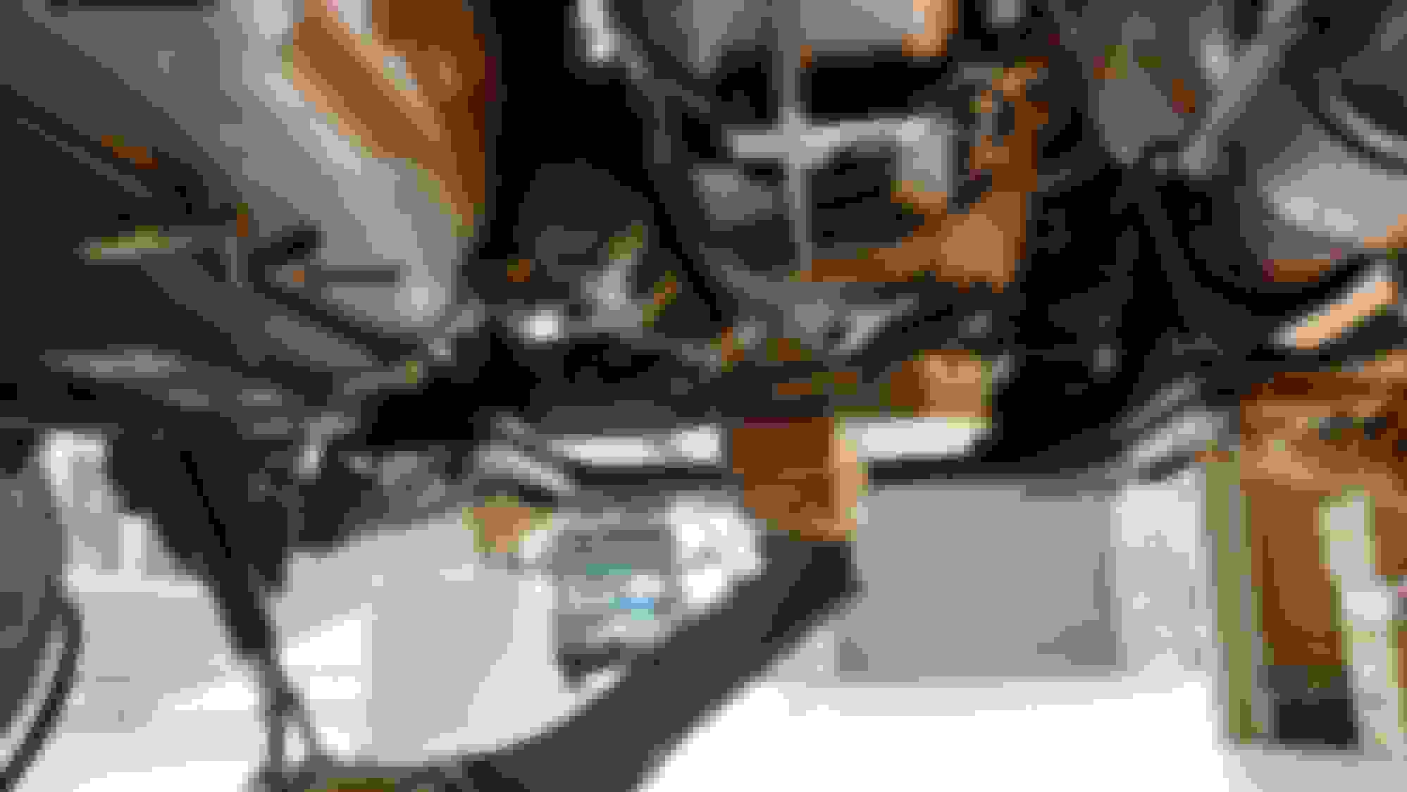
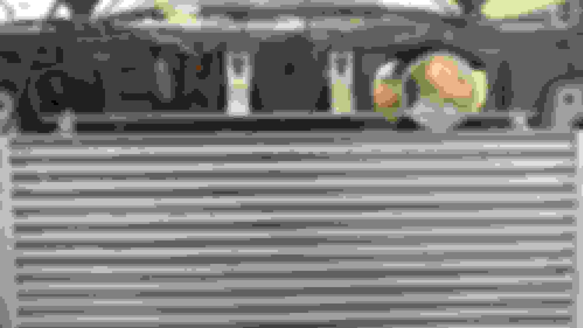
NOTE: I took this opportunity to address another challenge to achieving a tight mani seal. The OEM nut only has flats across the first ~1/2 of the nut.
- So, the nut is inaccessible straight on (d/t runners),
- inaccessible from beneath (d/t engine iron flange);
- leaving a ~ 45 degree window to access the nut.
- And since the nut only has flats on the first 1/2 of its width, the "grippable" portion recedes away as you tighten it. Perfect storm!
- bought standard 10x1.5mm nuts, but they didn't work for tight locations...too big, & require 17mm vs. 14mm wrench - ultimately resolved by:
1. modifying OEM nuts...ground off the flange so they c/b installed in backwards. (Brett, Thx for the best practice assist.) 2. purchased a “super-thin” wrench set, 1/8” thick:
- final config was to use the standard 10x1.5 nuts on easy access, upper mount locs, and OEM nuts w/ flanges ground off installed backwards on lower tight mount locs. - reassembled EVERYTHING, filled her w/oil and started her.
- Note: install / removal of the turbo and mani get somewhat easier as you learn the ins & outs of it w/ practice. Even fitted the turbine cover this time. - She fired right up & purred like a big cat. E-mani leak resolved!
Tight window to reach the lower ex-mani nuts.
. Two of three bottom ex-mani nuts are inaccessible w/ a standard 14mm wrench.
. My solution: modify the nuts fitted to the difficult access positions.
.
 09-29-2018, 09:45 PM


 and installed 175F oil cooler thermostats


 -->
--> 


 Trip to Lowes ...replaced with hard PVC coupler w/ cap.