When you click on links to various merchants on this site and make a purchase, this can result in this site earning a commission. Affiliate programs and affiliations include, but are not limited to, the eBay Partner Network.
Hey OD ...good to see you back !
Not an increase in boost ... a 2.5psi reduction in pressure drop across the intercooler. Was expecting approx. 1.5psi drop in turbine backpressure to accompany that but didn't see it , which was odd.
IATs are approx. 10C higher after a 14psi pull in 3rd gear vs previous same pull with previous intercooler.
Maf readings almost identical either way as were exhaust temps (reading obd cat temp) .
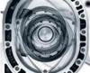
Something to consider in addition to what you've listed... comparing the two ICs from your pic. Looks like the new IC has ~2.5x the # of air channels, which are ~ � the length, and wider by ~ 15%. So, if we arbitrarily set the old runs at 24". Then the old IC will have cooling capacity: 13 runs x 24"x 1 unit ID = 312". The New IC will have cooling cap.: 33 runs x 6"x 1.15 ID = 228". By this…it seems we'd expect to see a trade-off of lower psi drop d/t shorter runs… at the cost of less overall cooling capacity.
Forgive my ignorance, why is pressure drop across the IC bad, if I am understanding this right, you don't want the turbo to move up the efficiency island to a less efficient cell or is there something else I am not getting.
Thanks
Something to consider in addition to what you've listed... comparing the two ICs from your pic. Looks like the new IC has ~2.5x the # of air channels, which are ~ � the length, and wider by ~ 15%. So, if we arbitrarily set the old runs at 24". Then the old IC will have cooling capacity: 13 runs x 24"x 1 unit ID = 312". The New IC will have cooling cap.: 33 runs x 6"x 1.15 ID = 228". By this…it seems we'd expect to see a trade-off of lower psi drop d/t shorter runs… at the cost of less overall cooling capacity.
That's true but there is more going on here than meets the eye ..........
*New IC will be using each individual cooling channel more efficiently ... That's because heat rejected will be distributed across the IC better . The old one had very long channels so heat rejection is better at beginning of the channel and tapers off towards the end as the air is cooler and the differential is less.
Also the new intercooler will flow air more evenly through the channels due to better end tank design. The old one will flow much more through the bottom channels that are in line with the air flow vs top channels which need the air to turn 90deg. twice.
*The new IC makes better use of the airflow through the bumper ...much of the old IC was blocked off by the x-member and lower bumper .
However ...the one thing that overides all that is that the mass of aluminium in the cooling channels for the old IC was almost double that of the new one . Meaning .... for a one off pull all that mass has ability to transfer heat from the air . This overides all the other design advantages of the new IC .... but only for that one pull . And only by about 7-8 degrees (after some improvements to ducting on new one).
I've noticed that he new IC recovers heaps faster than the old one did so is def more suitable for track use etc.
Forgive my ignorance, why is pressure drop across the IC bad, if I am understanding this right, you don't want the turbo to move up the efficiency island to a less efficient cell or is there something else I am not getting.
Thanks
Any pressure drop means that the turbo has to work harder to make the same boost which not only puts more heat into the air but means the turbine requires more backpressure . And more backpressure at the turbine means more exhaust carryover into the next combustion cycle = less power and more chance of detonation.
Any pressure drop means that the turbo has to work harder to make the same boost which not only puts more heat into the air but means the turbine requires more backpressure . And more backpressure at the turbine means more exhaust carryover into the next combustion cycle = less power and more chance of detonation.
Interesting find ...... I cut out 1/2 the diamonds on the grill , mainly to make the IC more visible but hoping it would improve cooling a little as well .
It actually improved IAT at cruise by a degree and after a run by two degrees. Would not have thought it would make that much difference but as this setup uses the airflow much better it seems it did.
Edit : IAT at 100km/hr cruise is only 2-3 deg C above ambient now !
That's true but there is more going on here than meets the eye ..........
*New IC will be using each individual cooling channel more efficiently ... That's because heat rejected will be distributed across the IC better . The old one had very long channels so heat rejection is better at beginning of the channel and tapers off towards the end as the air is cooler and the differential is less.
Also the new intercooler will flow air more evenly through the channels due to better end tank design. The old one will flow much more through the bottom channels that are in line with the air flow vs top channels which need the air to turn 90deg. twice.
*The new IC makes better use of the airflow through the bumper ...much of the old IC was blocked off by the x-member and lower bumper .
However ...the one thing that overides all that is that the mass of aluminium in the cooling channels for the old IC was almost double that of the new one . Meaning .... for a one off pull all that mass has ability to transfer heat from the air . This overides all the other design advantages of the new IC .... but only for that one pull . And only by about 7-8 degrees (after some improvements to ducting on new one).
I've noticed that he new IC recovers heaps faster than the old one did so is def more suitable for track use etc.
I can see all your points..., and of course maximizing bumper airflow is important; but why do you assert that the extra aluminum benefits the old IC ONLY in a single pull. Though the differential w/b diminishing b/c the runs are long, wouldn't this extra mass dampen temp rise to some degree always? Are there separators / dividers in the end tanks of your new IC?
I can see all your points..., and of course maximizing bumper airflow is important; but why do you assert that the extra aluminum benefits the old IC ONLY in a single pull. Though the differential w/b diminishing b/c the runs are long, wouldn't this extra mass dampen temp rise to some degree always? Are there separators / dividers in the end tanks of your new IC?
Because of heat soak .... Once that mass of AL. is heat soaked .... it doesn't do nearly as good a job as it did on the first pull .I've been on the dyno where we had to wait a good 5 mins before IATs came down to where they were on the first pull . Whereas the new IC recovers so quickly that heat soak isn't an issue.
And there are no dividers in the new IC ..... but it doesn't need them as much as typical end on ICs because the design works to promote even flow anyway .
just curious why you didnt consider using PWR intercooler
I was looking for something hi flow that wouldn't block the whole area in front of the radiator and would come out beside the intake . Eventually I found something from Treadstone that looked good but while trying to get them to explain their ridiculous shipping charges I found the one above and decided to give it a go. PWR didn't have the design I was looking for without doing a complete custom build ....so cost came into it in the end
And there are no dividers in the new IC ..... but it doesn't need them as much as typical end on ICs because the design works to promote even flow anyway .
can you share what this statement is based on?
most of the info I have read indicates the opposite from these style cores and they tend to be biased to one end. So much so that one local intercooler manufacturer found syphoning effects and reverse flow in the core. this was with inlet and outlet on the same side. Having the inlet and outlet on the opposite sides would improve flow distribution but i would guess the flow is still heavily biased to the outlet side.
You could be right .... was making an assumption based on info from Corky Bells' book and observations from the actual performance. I really need to test this with an infra red sensor to see if heat dispersion is even.
At 100km/hr steady state I see IATs 2-3 deg. C above ambient vs old IC which was 7-8 .Admittedly the new IC is better ducted than the old one but I would think at low flow this would be where this kind of issue would show up the most.
Rotorenvy .... was the IC you saw tested one with rectangular end tanks or a cast end tank tapered all the way along like my one ? Do you have a link to that material ?
How do you feel your theory/setup would work on a hybrid motor? Been considering using a hybrid renesis with peripheral exhaust ports running into the turbo and the side housing exhaust ports running the wastegate.
think it�d be worth running the center exhaust into the turbo also just because it�s there?
my other thought was to use a center housing from an rew or something with no exhaust in it so if just have the two outlets going to the turbo and the outside two would run the wastegate.
just theorizing here I feel like that method could work.
I think the idea of a hybrid Renesis is flawed in the first place . You have more exhaust area and timing than you will ever need . The biggest issue will be very poor response due to all that manifold volume plus the lack of any strong pulses to the turbo. There are a few combinations that may work if you don't mind the response though ... Using the siamese for the WG isn't one of them as it wont flow enough on it's own.
IMO .... the way to do it is to block off all the side exhaust ports . Fill up as much of the void area as possible with solid stainless and block off the exits. The remaining dead area will have minimal effect on performance.
Then you have the potential of a really good engine with excellent response and no limit on top end performance.
Coming home after doing some in gear logs the other day I accelerated out of a corner and straight away heard this horrible rattling noise (not detonation).
Engine was toast so I pulled it out only to find turbo was gone as well .
Just had the engine dismantled last night and found part of the siamese sleeve had been ingested by the engine and spat out into the turbo .
Pretty gutted about it all I have to say .
Was able to see how the E&J solid corner seals were going after only about 2000kms . Not good I'm afraid . They were already starting to dig into the exhaust port land and making a wear mark all around the iron.
The apex seal wear doesn't look great either . This engine wasn't going to last very long even if the siamese hadn't fallen to bits.
Suspect the E50 played a hand in both seal issues but I know with the RX8 corner seals and ALS apexs I definitely didn't see wear like this.
I recently got a "rattle" as well and also an oil leak between the front iron and house so I pulled it out and tore it down. No wear from the E&J seals, all apex seal surfaces have a mirror finish. Looks like I do have some exhaust port wear from the solid corner seals.
most of the info I have read indicates the opposite from these style cores and they tend to be biased to one end. So much so that one local intercooler manufacturer found syphoning effects and reverse flow in the core. this was with inlet and outlet on the same side. Having the inlet and outlet on the opposite sides would improve flow distribution but i would guess the flow is still heavily biased to the outlet side.
Decided you might be right so fitted a baffle ............
That looks good.
either way you were getting good results with pressure drop and cooling. I think much of the problems with vertical intercoolers is from having the inlets and outlets on one side. Having the aposing entrys is much better.
Will be a while before I test it , but if I get IATs down to similar to old intercooler ...it will be a big win !
I think the design of the end tanks is critical . The Treadstone one I looked at was same design as mine and rated for 1000hp . It has no baffle but a much narrower taper on the end tanks which I think would get more even distribution than mine.
Regarding your unexpected IATs with the new IC, I think the orientation of the modified outlet of your IC end tank is causing most of the charge air to flow through that side of the core. I.e. left side from driver seat, resulting in less cooling at higher flow rates. For symmetrical airflow across the core you'd want to leave the outlet in it's original horizontal orientation, though I see that there may not be room for that.
Regarding your unexpected IATs with the new IC, I think the orientation of the modified outlet of your IC end tank is causing most of the charge air to flow through that side of the core. I.e. left side from driver seat, resulting in less cooling at higher flow rates. For symmetrical airflow across the core you'd want to leave the outlet in it's original horizontal orientation, though I see that there may not be room for that.
I tend to think it's the inlet end tank design that's more the issue ...but the new outlet could be adding to the problem as well . Either way , I hope the baffle will help.
Check out the design of bottom tank (assume this is the inlet) for this 350z high flow IC : similar to Treadstone but even more pronounced taper .Note that inlet end tank taper starts before it even opens out into the tank.
Another high flow IC rated at 800hp ...similar end tank design as above.
Compare to mine : The tank area doesn't even go smaller than the 3" inlet area till about half way along the tank.
So ...I've finally tested the intercooler baffle . I get a 3 degree reduction in IAT from a temp rise of 20 degrees now down to 17C . Not good enough ...... so I'm thinking of setting up a test using a vacuum cleaner on blow and an infra red sensor .................... then playing with the end tank design ......
Depending on whether or not you modify the end tanks and how major that surgery is, you may want to try adding some features to trip the airflow as it enters each of the vertical channels to generate a more turbulence in the flow (assuming something like that isn't already present in the IC). Granted that will very likely increase pressure drop across the IC, but it should drive up rate of heat transfer and drop your IAT.
 11-11-2018, 01:18 PM