DIY: Throttle Body & Upper Manifold Removal (retitled)
 04-29-2010, 04:45 PM
#1
Registered
Thread Starter

DIY: Throttle Body & Upper Manifold Removal (retitled)
I need to check my throttle body and upper lower manifold and if need be clean them due to a oil problem i have.
Any one no if there's a detailed thread on how to do this task as i wont to stop any future problems .
Thanks for any help given.
Any one no if there's a detailed thread on how to do this task as i wont to stop any future problems .
Thanks for any help given.
 04-29-2010, 05:33 PM
#2

No detailed DIY that I know of, but I can try to describe the best I can...
Throttle Body:
1) Disconnect the electrical connection to the TB.
2) Remove the four long bolts on the front of the TB.
3) Leave the coolant hoses attached and swing the TB out of the way.
UIM (Upper Intake Manifold)... going off of memory:
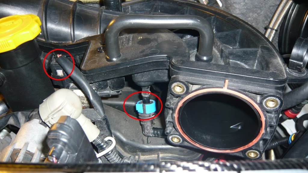
1) Remove electrical connection to purge solenoid (front-centered on UIM... to the right of the oil filler neck).
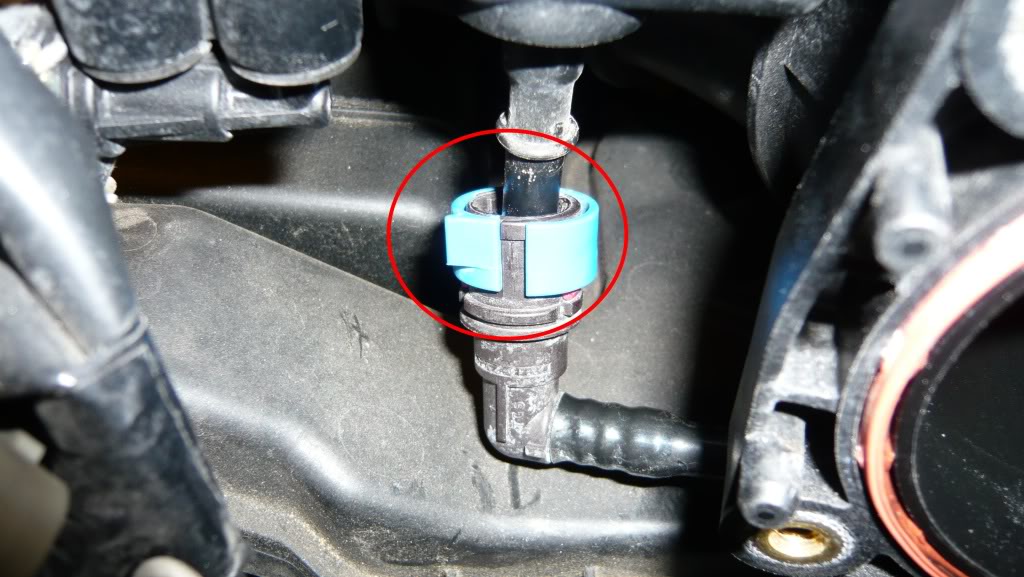
2) Underneath the purge solenoid you'll see a line with a blue disconnect, remove that.
3) Standing on the drive's side of the car, right behind where the TB was mounted, is a fitting for the VFAD.
...3a) If you still have a VFAD, remove hose.
...3b) If you don't have a VFAD, ignore because it should be capped
4) Like how the VFAD fitting is position underneath, run your hand under the UIM and around the first bend, you'll feel another hose that is used for a vacuum chamber for the AIR, SSV, and VDI solenoids. Remove that hose.
5) On top of the UIM is a thicker hose for the brake booster. Loosen clamp with pliers and move it away from fitting. Disconnect hose.
6) Look between and below UIM and brake booster... you'll see two lines, one with a red clip and the other with a blue clip (blue clip line is the other end of what you disconnected earlier). You'll see they are attached to a 90 degree bracket with "zip ties". Separate the lines from the bracket (DO NOT disconnect lines, just separate them from the bracket).
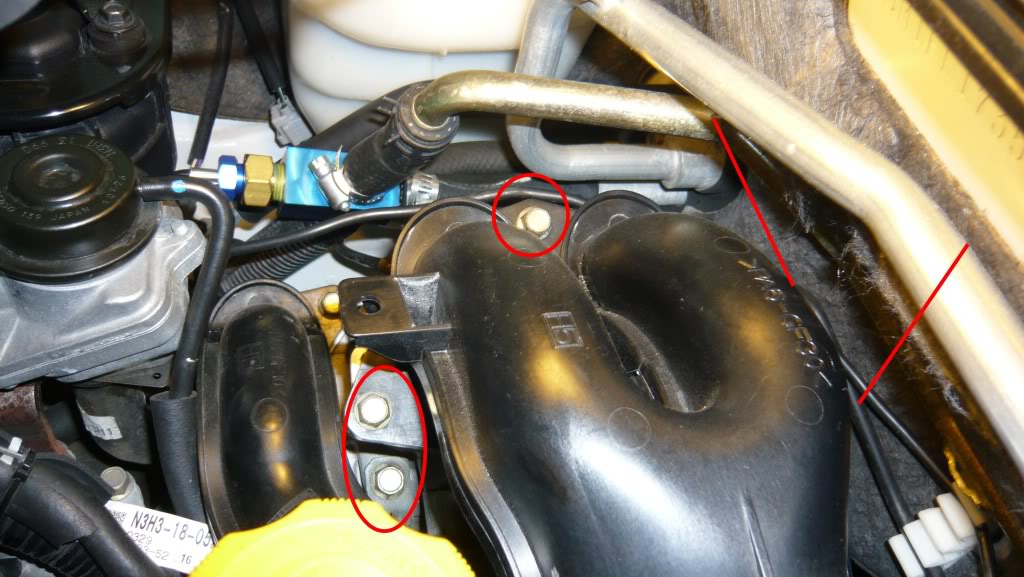
7) Here is a tricky part... behind the bracket are two bolts that attaches the oil neck to the bottom of the UIM. Easiest way to get to these bolts is to take pliers and bend the bracket up (basically straightening it). Then the bolts will be visible and easier to reach. Remove the two bolts.
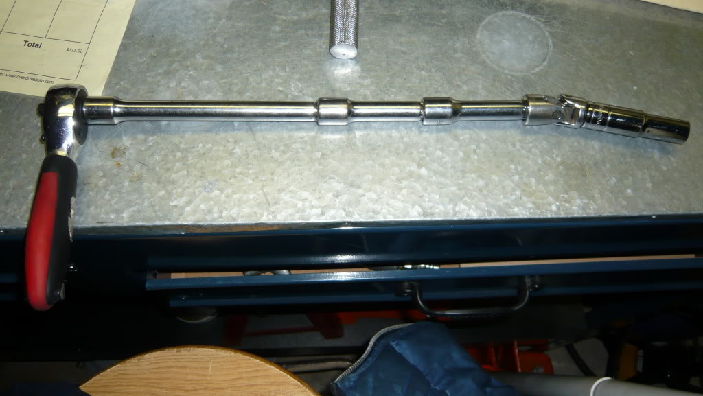
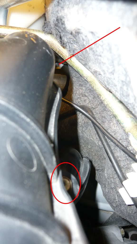
8) At the other end of the UIM where it connects to the LIM, remove the three bolts. The one against the firewall is the trickiest. A ratcheting wrench helps, but I've got a good combination that works consisting of a socket -> short extension -> u-joint -> long extension -> socket wrench. Experiment with what you got.
9) Once the three bolts are removed, look towards the center of the UIM and you'll see two bolts, one on each side, connecting the UIM to the auxiliary runners.
Remove the two bolts. (the one against the firewall is tricky too, but easier).
...NOTE: No need to remove the bolts securing the auxiliary runners to the LIM yet... wait until the UIM is removed for easier access.
10) Once you get those two bolts out, remove the oil fill cap and lift the UIM out (then put the oil cap back on).
11) Now you can remove the four bolts (two on each side) that attaches the auxiliary runners to the LIM.
12) You're done... so grab a beer!
Next time I have mine off I'll try to remember to take pics for a proper DIY.
LIM (Lower Intake Manifold)... Don't bother. Too much work and requires removing the engine. Its been done without removing the engine, but it was VERY tricky.
Only "oil in intake" issues with the LIM is the SSV, but there is a separate DIY for removing and cleaning just that valve so the whole LIM doesn't need to be removed.
Throttle Body:
1) Disconnect the electrical connection to the TB.
2) Remove the four long bolts on the front of the TB.
3) Leave the coolant hoses attached and swing the TB out of the way.
UIM (Upper Intake Manifold)... going off of memory:
1) Remove electrical connection to purge solenoid (front-centered on UIM... to the right of the oil filler neck).
2) Underneath the purge solenoid you'll see a line with a blue disconnect, remove that.
3) Standing on the drive's side of the car, right behind where the TB was mounted, is a fitting for the VFAD.
...3a) If you still have a VFAD, remove hose.
...3b) If you don't have a VFAD, ignore because it should be capped
4) Like how the VFAD fitting is position underneath, run your hand under the UIM and around the first bend, you'll feel another hose that is used for a vacuum chamber for the AIR, SSV, and VDI solenoids. Remove that hose.
5) On top of the UIM is a thicker hose for the brake booster. Loosen clamp with pliers and move it away from fitting. Disconnect hose.
6) Look between and below UIM and brake booster... you'll see two lines, one with a red clip and the other with a blue clip (blue clip line is the other end of what you disconnected earlier). You'll see they are attached to a 90 degree bracket with "zip ties". Separate the lines from the bracket (DO NOT disconnect lines, just separate them from the bracket).
7) Here is a tricky part... behind the bracket are two bolts that attaches the oil neck to the bottom of the UIM. Easiest way to get to these bolts is to take pliers and bend the bracket up (basically straightening it). Then the bolts will be visible and easier to reach. Remove the two bolts.
8) At the other end of the UIM where it connects to the LIM, remove the three bolts. The one against the firewall is the trickiest. A ratcheting wrench helps, but I've got a good combination that works consisting of a socket -> short extension -> u-joint -> long extension -> socket wrench. Experiment with what you got.
9) Once the three bolts are removed, look towards the center of the UIM and you'll see two bolts, one on each side, connecting the UIM to the auxiliary runners.
Remove the two bolts. (the one against the firewall is tricky too, but easier).
...NOTE: No need to remove the bolts securing the auxiliary runners to the LIM yet... wait until the UIM is removed for easier access.
10) Once you get those two bolts out, remove the oil fill cap and lift the UIM out (then put the oil cap back on).
11) Now you can remove the four bolts (two on each side) that attaches the auxiliary runners to the LIM.
12) You're done... so grab a beer!
Next time I have mine off I'll try to remember to take pics for a proper DIY.
LIM (Lower Intake Manifold)... Don't bother. Too much work and requires removing the engine. Its been done without removing the engine, but it was VERY tricky.
Only "oil in intake" issues with the LIM is the SSV, but there is a separate DIY for removing and cleaning just that valve so the whole LIM doesn't need to be removed.
Last edited by Jon316G; 05-02-2010 at 06:00 PM.
The following 5 users liked this post by Jon316G:
animan430 (03-30-2022),
OHLOOKANEAGLE (09-28-2020),
Rx8new (10-24-2022),
Tamas (07-12-2022),
Zerg_Rush (09-12-2018)

The following users liked this post:
OHLOOKANEAGLE (09-28-2020)
11-23-2010, 02:25 PM
#5
Hey Jon,
I know you did this from memory .... just thought I would add some to it for posterity
I'm working on a 05 MT
Note about section 1: I think if you are stock you don't have to necessary unplug MAF electrical connection but its nice to get out of the way.
1A) Remove the hose clamps around the rubber according tube
1B) Remove rubber tube
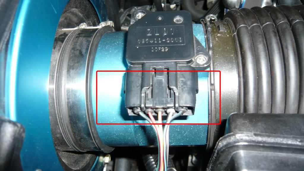
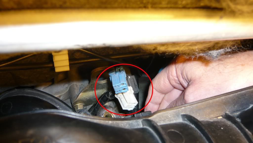
Note about 2: These connectors can be tricky and always feel like they are going to break to me. To remove these connectors push blue clip on the one side back until you feel it click. Connector should now be free to disconnect.
I coudn't find the Air, SSV, VDI air as discribe above, or at least it doesn't seem to be in the same location.
The way it seem to be setup on mine 05 was 3 seperate vacuum hoses along with an electrical connector for each the Air, SSV and VDI solenoids. I found it easier to remove these after the UIM was free and I could get my arm down in there.
I was able to reach mine without having to do this, a long 12" extension works nicely.
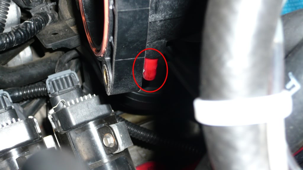
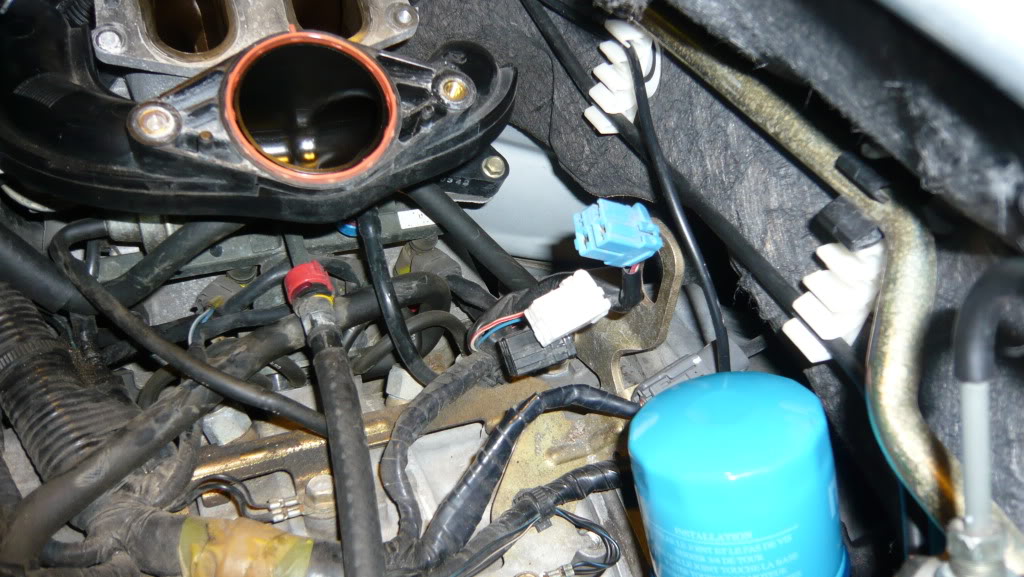
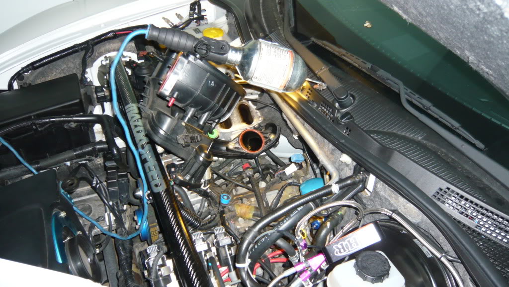
Top of UIM

Tricky bolts

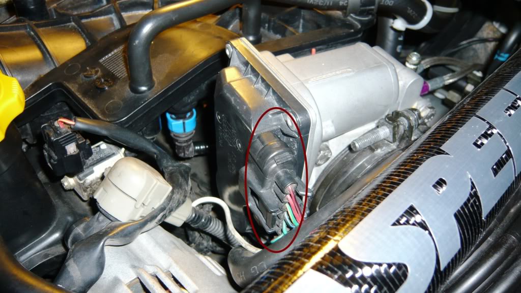
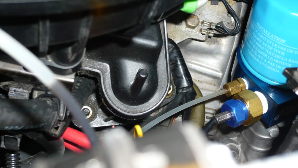
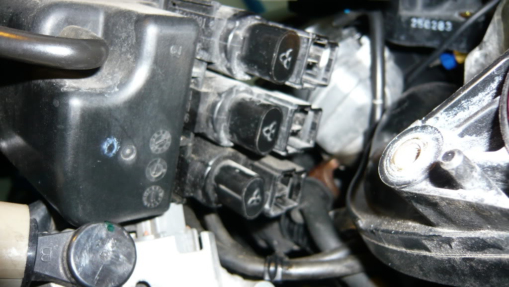
I choose this time to remove the Air, SSV, and VDI vacuum hoses and connectors. The connectors have a little tab on the top toward the passenger side. Pull and hold the tab in then disconnect.
The Reach Around
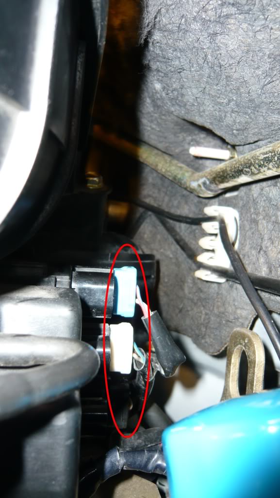
Connector terminals at the rear
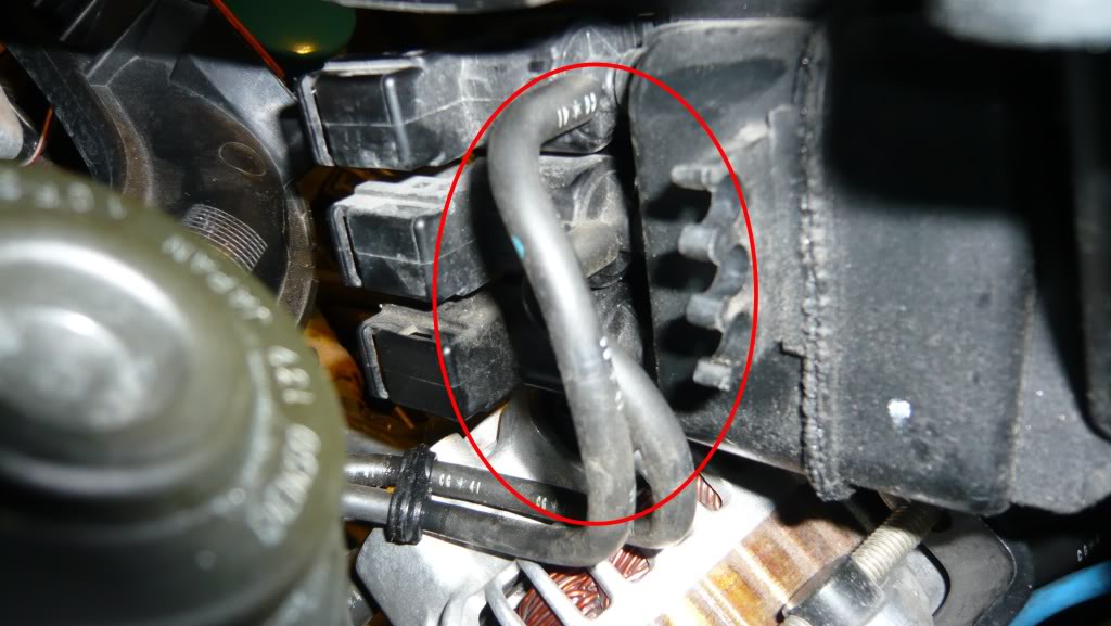
Vacuum hose connectors - picture from front, with one hose removed already
I grabbed two beers because I have a problem ....
I know you did this from memory .... just thought I would add some to it for posterity
I'm working on a 05 MT
Throttle Body:
1) Disconnect the electrical connection to the TB.
1) Disconnect the electrical connection to the TB.
1A) Remove the hose clamps around the rubber according tube
1B) Remove rubber tube
2) Remove the four long bolts on the front of the TB.
3) Leave the coolant hoses attached and swing the TB out of the way.
UIM (Upper Intake Manifold)... going off of memory:
1) Remove electrical connection to purge solenoid (front-centered on UIM... to the right of the oil filler
neck).
2) Underneath the purge solenoid you'll see a line with a blue disconnect, remove that.
3) Standing on the drive's side of the car, right behind where the TB was mounted, is a fitting for the
VFAD.
...3a) If you still have a VFAD, remove hose.
...3b) If you don't have a VFAD, ignore because it should be capped
4) Like how the VFAD fitting is position underneath, run your hand under the UIM and around the first bend,
you'll feel another hose that is used for a vacuum chamber for the AIR, SSV, and VDI solenoids. Remove that
hose.
I coudn't find the Air, SSV, VDI air as discribe above, or at least it doesn't seem to be in the same location.
The way it seem to be setup on mine 05 was 3 seperate vacuum hoses along with an electrical connector for each the Air, SSV and VDI solenoids. I found it easier to remove these after the UIM was free and I could get my arm down in there.
5) On top of the UIM is a thicker hose for the brake booster. Loosen clamp with pliers and move it away
from fitting. Disconnect hose.
6) Look between and below UIM and brake booster... you'll see two lines, one with a red clip and the other
with a blue clip (blue clip line is the other end of what you disconnected earlier). You'll see they are
attached to a 90 degree bracket with "zip ties". Separate the lines from the bracket (DO NOT disconnect
lines, just separate them from the bracket).
7) Here is a tricky part... behind the bracket are two bolts that attaches the oil neck to the bottom of
the UIM. Easiest way to get to these bolts is to take pliers and bend the bracket up (basically
straightening it). Then the bolts will be visible and easier to reach. Remove the two bolts.
8) At the other end of the UIM where it connects to the LIM, remove the three bolts. The one against the
firewall is the trickiest. A ratcheting wrench helps, but I've got a good combination that works consisting
of a socket -> short extension -> u-joint -> long extension -> socket wrench. Experiment with what you got.
9) Once the three bolts are removed, look towards the center of the UIM and you'll see two bolts, one on
each side, connecting the UIM to the auxiliary runners.
Remove the two bolts. (the one against the firewall is tricky too, but easier).
...NOTE: No need to remove the bolts securing the auxiliary runners to the LIM yet... wait until the UIM is
removed for easier access.
10) Once you get those two bolts out, remove the oil fill cap and lift the UIM out (then put the oil cap
back on).
Tricky bolts
I choose this time to remove the Air, SSV, and VDI vacuum hoses and connectors. The connectors have a little tab on the top toward the passenger side. Pull and hold the tab in then disconnect.
The Reach Around
Connector terminals at the rear
Vacuum hose connectors - picture from front, with one hose removed already
11) Now you can remove the four bolts (two on each side) that attaches the auxiliary runners to the LIM.
12) You're done... so grab a beer!
12) You're done... so grab a beer!
I grabbed two beers because I have a problem ....
The following 2 users liked this post by wcs:
1Sontov (10-11-2017),
Fernando99 (03-05-2024)

The following users liked this post:
Fernando99 (03-05-2024)
11-23-2010, 02:58 PM
#7
LOL
I couldn't believe how easy it was .... Only took about 2ish hours to tear down and put back together.
Hardest parts where trying to unplug those solenoid connectors and not damaging that darn oil pressure tube.
LOL thinking about it .... I only ever used the 10mm socket! How awesome is that?!
I couldn't believe how easy it was .... Only took about 2ish hours to tear down and put back together.
Hardest parts where trying to unplug those solenoid connectors and not damaging that darn oil pressure tube.
LOL thinking about it .... I only ever used the 10mm socket! How awesome is that?!

 ... those two bolts are the only thing holding me back
12-26-2010, 10:35 PM
... those two bolts are the only thing holding me back
12-26-2010, 10:35 PM
#10
SARX Legend
iTrader: (46)


 12-27-2010, 07:26 AM
#16

Those suckers where in there tight ... real tight ... I think they actually did have loctight on them.
Just make sure the socket fits snugly before you lean in to it ... rounding the head on those nuts would be a bitch.


 12-19-2011, 10:31 AM
#20

Jon, your help has been monumental in assisting me remove & clean the APV barrels, the SSV and the VDI valve.
Do you recommend trying to clean the interior channels (there may be a better phrase here) of the LIM? Is there an effective way to do this?
Do you recommend trying to clean the interior channels (there may be a better phrase here) of the LIM? Is there an effective way to do this?
05-24-2013, 09:32 AM
#21
Registered

Join Date: Jul 2006
Posts: 36
Likes: 0
Received 0 Likes
on
0 Posts
Thanks alot for this thread. It's been very usefull.
For other readers, here is one more threads on this forum that I've also found usefull.
https://www.rx8club.com/series-i-tec...-244654/page2/
Also for information: I've found that the two bolts on the upper intake manifold (next to throttle body) that hold a bracket for two cables, are easier to remove if you jack the car and use a long extention from underneath the car.
Now that I've had the experience of having it done once. Let me know if you need any help. Who know, I might be able to give good advise.
Oh and the two nasty botls near the firewall. Use a universal joint. Much easier.
06-07-2013, 02:24 PM
#22

Does anyone have a diagram or pic of how the three vacuum hoses behind the UIM go back. I put mine back and think I may have mixed up 2 hoses. Cars running fine but I have a CEL for the air pump and when shutting the car off, I hear a "Brrrrr" noise sounding like the air pump.
 08-06-2013, 05:18 PM
#24

Awesome DIY!
I would add two things.
1.) Before you can lift the UIM out of the engine bay, you'll have to unclip the small wiring harness from the front-middle part of it.
2.) Before reinstalling the UIM, take the dipstick out. It's very easy to get the UIM caught on the dipstick loop and bend it.
I would add two things.
1.) Before you can lift the UIM out of the engine bay, you'll have to unclip the small wiring harness from the front-middle part of it.
2.) Before reinstalling the UIM, take the dipstick out. It's very easy to get the UIM caught on the dipstick loop and bend it.


