When you click on links to various merchants on this site and make a purchase, this can result in this site earning a commission. Affiliate programs and affiliations include, but are not limited to, the eBay Partner Network.
A couple months ago I bought a prepped RX-8 race car to replace my time trial car, which I destroyed quite thoroughly at Autobahn in a crash. I'm going through the car completely over the winter because...race car, right?
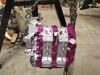
The previous owner had the ability to keep the battery in the stock location or mount it in the trunk, depending on the class and sanctioning body he was racing with on any given weekend. I'm going to clean up the wiring and some and free up space for cooling by permanently relocating the battery.
I also need to replace the engine. Thankfully I have one of those. But in disconnecting all the wiring and hoses and such, I found something I have a question about.
I have no idea what that two-pin connector on the top of the alternator does. It has been spliced so that, I believe, it can be disconnected with the main shutoff switch. I would have thought simply switching off the positive battery lead would have been enough, but this wire may be connected to the ignition somehow, if I have that right.
I'd appreciate some insight, though. I am a wiring dummy. Thanks!
That wire should be switched with the main kill switch. Use a 4-pole switch and connect it to the smaller poles. This ensures that when the kill switch is turned off, the car will not keep running on alternator power (even though the batter is disconnected). Will not pass most tech inspections without it.
The Electrical Manual is a separate book with all the wiring diagrams.
This is from the original service highlights manual:
Also, these wires are not what needs to connected to the kill switch per the diagram description above. If you go back to the wiring diagram, in addition to the pcm control wires there is another pair of connections, one to ground and the other being the main power supply output cable. It’s the power supply cable (the connection on the back of the alternator with the plastic protective cover) that needs to be tied into the kill switch.
As far as whatever the previous owner was doing, your guess is as good as mine.
Every kill switch I've seen or been involved with uses the alternator excite wire (as yours does). It achieves the same thing without the extra gauge wiring required to run the power supply cable. I'm not sure the kill switches are even rated for the power supply wire. The poles are pretty small.
Additionally disconnecting the alternator from the battery while it is running can do bad things (something about voltage spikes and diodes), so I'm told but this is getting out of my area of expertise.
Well I didn’t see it that way because unlike the past technology this alternator is computer driven. I don’t really see how that makes sense, so if someone can clarify why it does that’d be helpful to my understanding. Because if you kill the battery output and the generator output then how is there going to be an excite signal? I must be missing a key component of information and if so, please excuse my ignorance and educate me.
Ok, the deal is that there is no field wire on an RX8 alternator as indicated on that diagram just like a 1-wire self-exciting racing alternator doesn’t have one either. It won’t hurt anything to cut the pcm wire in like that, but it is accomplishing zip ...
Otherwise all the pcm does is control the output voltage regulation through those two wire per the diagram in post #8.
My electrical engineering days are too far gone to argue. But, when the W/G wire is disconnected (along with + battery), charging stops and the car dies. Perhaps the car would die without it but I haven't tried. This wiring diagram is the same as NB Miatas and it is also the wire that they use for the kill switch (Spec Miata).
The RX8 starting/charging wiring diagram was already attached in Post#4 above and the NB Miata doesn�t have a computer-controlled alternator.
You do understand that once both battery and alternator outputs are cut that there is not going to be any power available through those other wires because there is no power to the pcm, right? In the Longacre diagram the field wire has a direct connection to the positive battery post. When you set up the kill switch you have to run all the +battery connected paths through it, which there are three on an RX8 (assuming no additional wires were added); the main power to the 120A fuse which includes the alternator charging output path, EPS power to the 60A fuse, and the starter cable (B wire in post#4 diagram). There is no battery-direct field wire connection on the RX8 (see main wiring diagram below). All of the battery direct RX8 connections exceed the 20A limit of the small kill switch post though. So they all have to be tied into the large post side.
What about an output-only, 1-wire racing alternator? Do they ban those? Pretty sure they don�t.
Not trying to argue against the rules or not to do as your told and don�t ask questions; I get that. In post#11 I asked if someone could explain the reasoning behind the requirement being applicable in this case. I don�t believe there is one relative to having the factory alternator setup on an RX8.
Adding the diagram from post#4 here so it�s clear how the Starting & Charging Sytems tie into it
NB Miata alternator diagram (attached) is identical to the RX8 so I infer that it is computer controlled. I posted the RX8 diagram because the wire colors are listed. Here's how it was explained to me for the NB (I've change the wire descriptors to make it correct for the RX8), take it or leave it.
The W/G wire is the signal wire to the PCM. It is connected to one of the three stators so it senses whether or not the alternator is turning. The BR/R wire is the signal wire from the PCM to the exciter. If the alternator stops turning, there are no pulses on the W/G wire so the PCM cuts signal to the BR/R wire disabling the exciter and turns on the ALT warning light (presumably).
So cutting the W/G wire triggers the PCM to disable the internal exciter and charging stops.
Now I'm going to have to disconnect this wire on my car to prove the theory.
it still ignores the basic fact that once you throw the kill switch that there is no power being supplied to the excite wire. It doesn’t matter if the stator is turning or not. Both input and output are dead without running the input back through the kill switch a second time.
In the case of the NB the alternator itself is not computer controlled. The PCM is switching the excite relay wire on/off, but again per the previous statement once you throw the kill switch on the two larger main posts that wire is already dead without doing anything else. Putting it through the kill switch a second time makes it redundant without serving any useful purpose. Otherwise you could argue that it needs to be a 6-post switch with the main power run through twice too.
Just to be clear, the difference between the RX8 and Longacre diagram is that both the charge wire and the excite/field wire (if you want to call it that) run through the electrical system distribution block. Because the RX8 alternator needs the pcm to modulate the voltage output that wire can’t run direct to the +battery post like in the diagram.
Ok, did some research. As far as the SCCA is concerned the GCR only requires you to have a kill/master switch and that the entire electrical system be shut down from the battery and alternator including any possibility of the engine operating. There is no specific pole or wiring requirement etc. beyond accomplishing that end goal. On older style generator/operators you could fry diodes and such depending on how the whole thing was wired and so they ran the excite wire to those other smaller poles. However, what the diagram doesn’t show is the switch also has to be grounded and when turned off those smaller poles don’t just separate, the field wire input goes to ground to divert the generator/alternator spike/surge energy if the engine is running. Otherwise there are numerous different ways to wire a master switch depending on the vehicle/circumstances with pros and cons for all. I saw at least 5 or 6 master switch diagram types listed on one of the divisional website tech page, but they are suggestions/examples, not requirements.
What you wrote in #17 makes sense to me. Although my wiring theory is probably sound, as you point out, it's redundant since there is no power from ECU to alternator. I'll probably verify this next time I have the car running but it simplifies my wiring if I ever decide to rewire. In order to get a log book for a new car build, I only have to prove that when the kill switch is thrown, a running car immediately dies (which it does). No one checks wiring because it varies so much by car.
It looks like that signal wire BR/R is actually connected to the field coil in the alternator. The PCM controls the field current to control the output voltage of the alternator. In essence, switching this wire (to ground) is serving the same purpose of killing the field wire in older systems.
The PCM should ground the field coil when power is no longer applied. However, it doesn't hurt to ground it with a kill switch, in the event that its output is undefined during the instantaneous moments after (brownout) when the kill switch is turned off.
Killing the W/G signal wire would not be the wire to disconnect in this case, as the state of the BR/R wire is then dependent on the PCM (which logically, should be ground).
EDIT: Misspoke; you'd need to drive the BR/R signal HIGH (as in, whatever the PCM high signal is) to turn off the field coil. Pulling the signal line to ground will cause the field coil to discharge itself (at a slightly slower rate) through the diode. If the alternator is opened when the switch is cut (no connection to any load) it would be a bad idea to drive the signal high, as then the alternator would attempt to drive the field coil...
EDIT EDIT: Hurp derp, over-thinking this -- no current through field coil = off, so drive signal wire low to turn off field coil.
Last edited by gigglehurtz; 11-26-2017 at 01:01 PM.
Reason: Improving signal to noise ratio
The service manaul states that key-on/engine off the wire has 1 Volt power, engine running at idle the range is 3 - 8 Volts, and then varies by load from there. The new Adaptronic modular RX8 ecu alternator control program indicates that there is a 4 Volt control range, which makes sense.
My position is that the ecu already performs this function so once you cut power to it the same thing is already occurring without needing the master switch connection. If you don’t cut power to the pcm it will start causing issues for sure. A number of people here have fried wiring and alternators by not having the alternator charge wire connection (nut under the plastic flip-top protector guard) tightened fully.
I was looking at Bosch Motorsports catalog today and it states that their alternators are configured with special zenar diodes to handle dump surge without damage. Just thought I’d mention it since it was relevant in a general sense.
Adding more info, came across this solid-state disconnect setup that supports the general discission on output wire only for the alternator and is more in line with current technology and design practices:
This one is a bit pricey though; $345. Iron Canyon Motorsport sells a more generic version that supposedly has an improvement over this one, but it’s still $300.
CARTEK BATTERY ISOLATOR
The GTs Battery Isolator from CARTEK is a very small and highly reliable alternative to the traditional mechanical master-switch and has been designed to overcome all of the problems and restrictions associated with mechanical and electro/mechanical safety cut-outs.
When fitted to a race car our Solid State Battery Isolator simultaneously isolates the battery and kills the engine immediately when triggered in accordance with FiA safety regulations.
This system has been designed to simplify installation thereby saving time and reducing build costs.
Features
Fully electronic with no moving parts
Totally sealed against water and dirt
Completely resistant to shock and vibration
Fully integrated with built in alternator run-down circuitry - No extra components required
Driver operation by a single internal ON-OFF button/switch
External operation by single or multiple 'strike' button(s)
Buttons / switches connected to Isolator using light weight wiring
Mounts close to battery for reduced cabling
Very small and weighs just 120g
Designed and manufactured in UK using high quality components
How it Works (diagram below is interative, click on the connection points)
The Cartek Battery Isolator GT provides two functions. The first is to disconnect the Battery from all Electrical Circuits. The second is to kill the engine.
Battery Isolation
The Battery Isolators work by being fitted in between the negative side of the battery and the chassis ( As seen above ). When the external kill button has been activated or the internal button been switched to the off state, then the Battery Isolator will disconnect the negative side of the battery from the Chassis. This means that no power can get to any of the electrical circuits as there is a break in the circuit.
Engine Kill
The Cartek Battery Isolator GTs kills the engine by taking in a fixed 12v input and sending a 12v output that would power your Ignition or ECU. When the negative side of the battery has been disconnected it will also cut the 12v output powering your Ignition or ECU. This will kill the engine.
Built in Protection
The Cartek Battery Isolator GT comes with built in alternator run down protection meaning no extra wiring and no extra components.
How Is It Controlled?
The two electronic isolation circuits are controlled by microprocessors and incorporate various safety systems including over-temperature and over-current monitoring. These microprocessors also monitor the kill switches/buttons for instant activation without false triggering.
 11-21-2017, 09:40 AM