RxDuino: Development Chat
 06-13-2011, 05:50 PM
#1

Contents
- Intro - Page 1
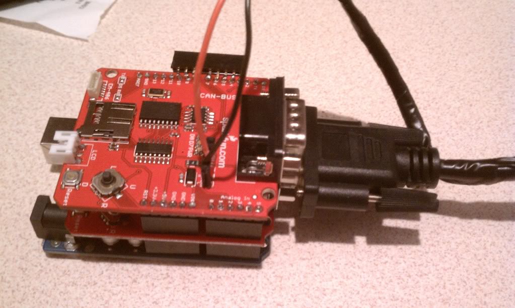
- Rev.1 Hardware Photos - Post 17
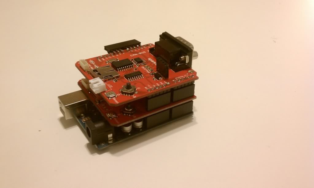
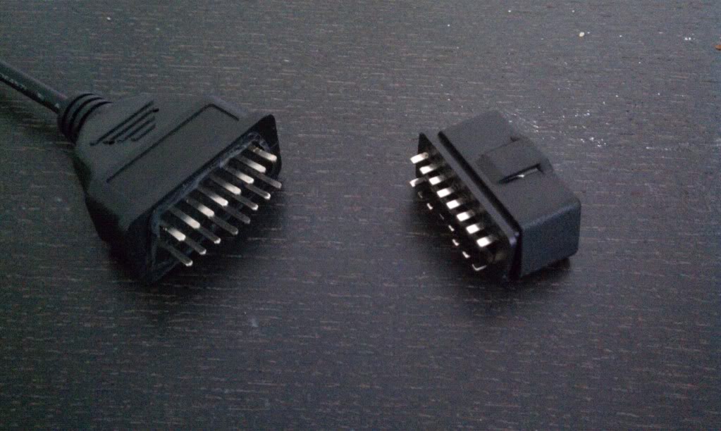
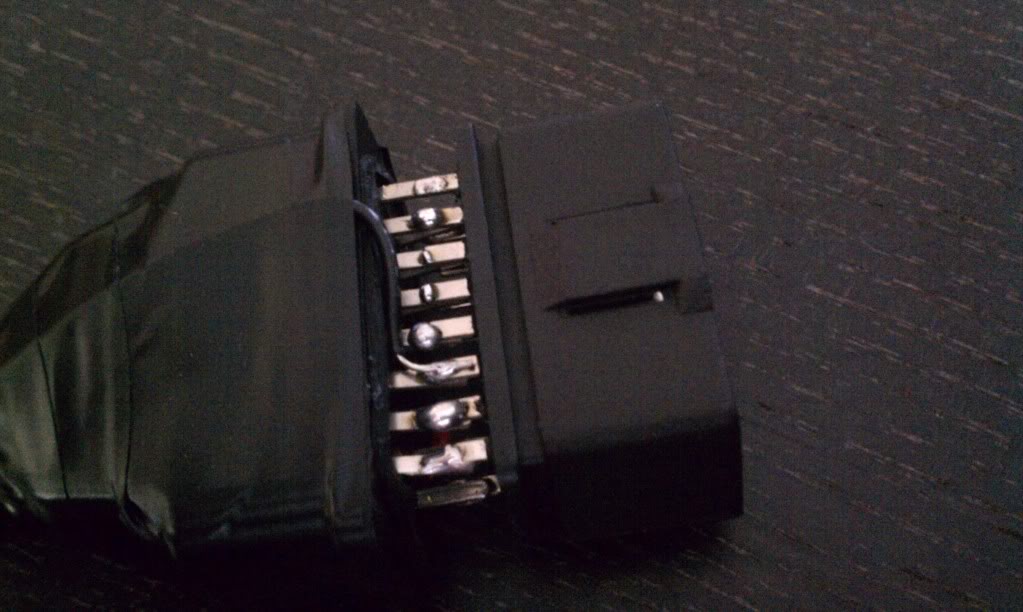
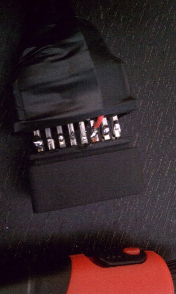
- OBD2 Cable Integration - Post 20
- First Message To M.I.D. - Post 22
- Live Data Monitoring on M.I.D. - Post 29
- Software Version 0.5 (Custom Text) - Post 42
- Rev.2 Hardware Photos (Bluetooth Integration) - Post 69
- Android Logging - Post 74
- MSCAN Testbed - Post 77
- Software Update (Wheel Speed Monitor) - Post 101
- Software Version 0.9 (TPMS and Temps) - Post 114
- Reading Cruise Control Signal - Post 128
- Integrating Cruise Control Buttons - Post 139
- Fab Design Layout - Post 155
- Console Application Design - Post 168
- Hardware Revision 1.2 Design - Post 214
- Hardware Revision 1.2 Layout - Post 222
- Hardware Revision 1.3 Design - Post 226
- Hardware Revision 1.4 Design - Post 254
- Enclosure Prototype - Post 295
- Assembled Enclosure - Post 311
Project Status
- Protyping is complete!
- Software is complete!
- Enclosure is complete!
- Track testing is complete!
- Instruction Manual in progress
Purchase Information
Once the product has been finished, I will be working with the admin's and mods of rx8club.com to set up vendor status and a group buy.
Project Information
http://www.normalexception.net/index...canbus-scanner
Project Roadmap
http://www.normalexception.net/redmi...xduino/roadmap
Introduction
As a computer engineer, I have a very high addiction to hardware, software, and data collection. If there is a piece of hardware that is worth tinkering with, I try my best to get my hands on it and give it a try. For my thesis work, I have played around with the TelosB development boards, and used the TinyOS operating system as a basis for development.
Spending so much time with my car, I have really grown to understand the ins and outs of how the actual mechanics of the car work, but I have been very curious to investigate the software communications that happen. One idea was to purchase a premade obd2 scanner and just view data, but I wanted to go a step further.
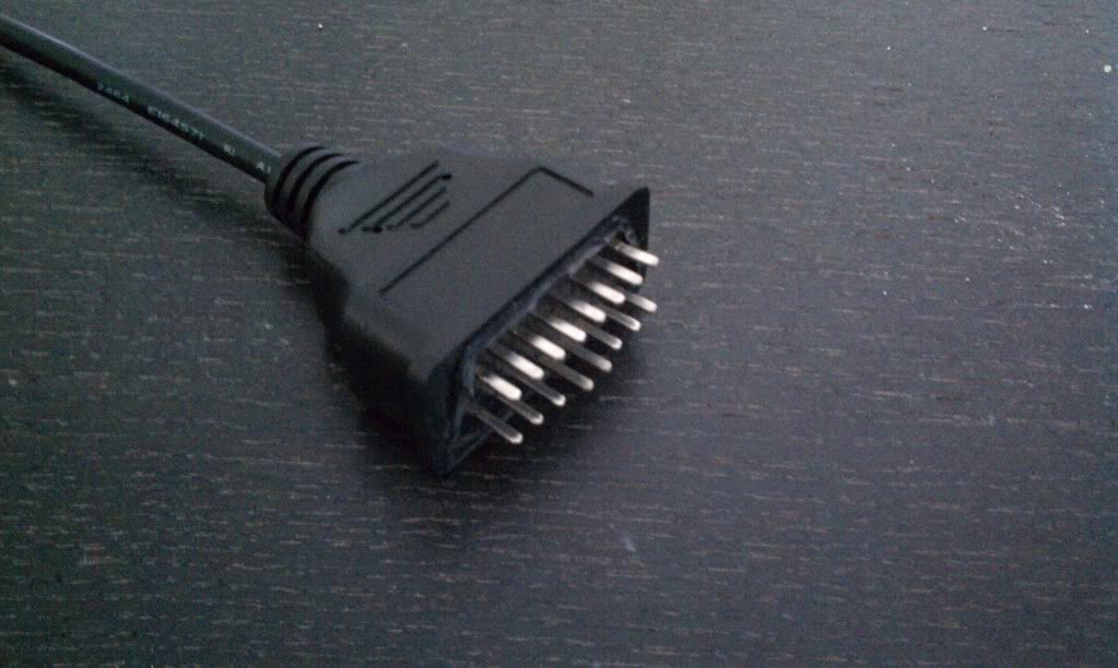
During my investigation of trying to get my LCD to properly display the time and temperature after changing out the stock radio, I came to understand how the LCD actually works. Residing on a CANBUS, the LCD is primarily communicated with by each peripheral on the network talking to a specific address. Just like how one can retrieve information from the ECU, I wanted to see if I could actually go a bit further and not only scan for information, but also display some important information on my LCD screen.
In doing this research, I came across the Arduino boards. I have always heard a lot of buzz around these boards, but have never had a need to actually get my hands on one. After finding out that these are a perfect light weight development board, as well as an available CANBUS interpreter, it was exactly what was going to suit my needs.
The first step was to actually design a board and some software to get some information out of the OBD2 port. The first thing I did, was to take a simple stupid application just to get some data.
Once I confirmed that I could actually read some data at a reasonable rate, I decided to spice up the GUI a bit and read some more information, through multiple montiors
So far so good, except I found that by having 6 monitors at a time, I get a bit of LCD lag. I will either need to fabricate a lower latency serial bus for the LCD, or do what I decided, and just display 4 at a time.
I will keep you guys updated as time goes. I have some more hardware coming so that I can easily display more info, as well as some tools to fab my own OBD2 cable to communicate to the MSCAN. Let me know what you guys think so far, and feel free to throw in some suggestions.
Last edited by paimon.soror; 04-20-2012 at 11:46 AM. Reason: Image and Purchase Info

 06-13-2011, 08:43 PM
#4
Registered
iTrader: (1)

Join Date: Oct 2007
Location: Boston, MA
Posts: 193
Likes: 0
Received 0 Likes
on
0 Posts
Subscribed! I love the arduino board. I used it to regain button functionality on the OEM nav dash piece and some other minor carputer tasks.
I also just moved to an R3 and will def be installing a carputer on it at some point. Your project is of a lot of interest for me.
You should actually work with MazdaManiac on trying to get that freaking accessport work in S2 cars
I also just moved to an R3 and will def be installing a carputer on it at some point. Your project is of a lot of interest for me.
You should actually work with MazdaManiac on trying to get that freaking accessport work in S2 cars

 06-13-2011, 09:30 PM
#7
Thanks guys, no worries I will keep you guys update as I make progress. If anyone has a good idea on how I can multiplex the two busses that would be great. I was intending to grab a simple AD multiplexer, but it really isn't that easy since the canbus doesn't operate on a digital TX/RX but on an analog HI LO pinout.
Thinking I probably need two muxers
Mx = Mux X
Cx = Channel X
M1C1 = HS High
M2C1 = HS Low
M1C2 = MS High
M2C2 = MS Low
Sx = Select X
M1S1 = M2S1 = Arduino pin D1
M1S2 = M2S2 = Arduino pin D2
M1S3 = M2S3 = Arduino pin D3
M1S4 = M2S4 = Arduino pin D4
So essentially when I pass in 1000 to my selects I will be getting M1C1 and M2C1 enabled, and so forth...
Last edited by paimon.soror; 06-13-2011 at 09:43 PM.

 06-14-2011, 12:13 AM
#9
Registered

Join Date: Oct 2010
Posts: 105
Likes: 0
Received 0 Likes
on
0 Posts
sweet. I was looking into getting into the arduino and i was thinking of doing the same thing. haha. Apparently the android phones can interface with an arduino board as well, so that could be fun.
 06-14-2011, 09:02 AM
#11
Or instead of having buttons like the goodbox, we could use the android phone as a remote, have a small app running that has a "d-pad" like interface, and when you touch that it changes the display on the lcd....
but thats all thoughts for the future, my first goal is actually getting this stuff displaying on the screen.
 06-14-2011, 12:15 PM
#13
I zoom therefore I am.

Or instead of having buttons like the goodbox, we could use the android phone as a remote, have a small app running that has a "d-pad" like interface, and when you touch that it changes the display on the lcd....
but thats all thoughts for the future, my first goal is actually getting this stuff displaying on the screen.
but thats all thoughts for the future, my first goal is actually getting this stuff displaying on the screen.
 06-20-2011, 09:01 AM
#15
I was actually doing some thinking and thought about what rafaga said about the AP for S2's. Not so much about the maps, but moreso about the masking of a MIL code. Not sure if he has come across this thread, but anyone (MM) know what methods the AP is actually using to mask an error code (mainly the cat.efficiency codes for those guys who want to run catless)? Could it be as easy as writing some data at a certain address on the ECU? I found the address and command to reset the MIL status.
I will post up some pics when I get home of the progress of the circuit.
 06-20-2011, 08:41 PM
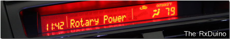
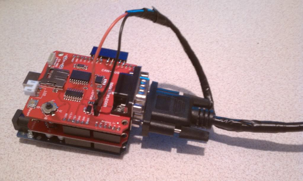
#17
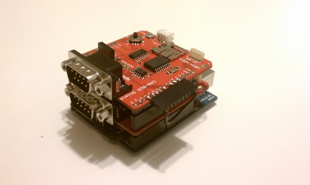
Heres the pics I promised. The top layer is the MSCAN circuit while the middle layer is the HSCAN circuit. The bottom layer is the arduino development board. For those that understand tech jargon and want to know more about what is going on at the top layer with the headers ... thats a rewire of pin 10 (default chip select) to pin 3. This way I can software select which CAN to communicate to depending on what chip I enable via SPI.
I will keep you guys posted. Crossing my fingers that this ends up working out.

 06-21-2011, 06:36 PM
#21

I've said it before, and I'll say it again: You, sir, and your "outside the box" thinking is a credit to the forums!!
I know that you've seen this with other products (GB, etc), and call it "borrowed ideas". But, to actually pursue your projects is what I admire You're bringing a new strain of hope to SII owners lol Maybe Cobb AP for SII isn't too far away, after all...
I know that you've seen this with other products (GB, etc), and call it "borrowed ideas". But, to actually pursue your projects is what I admire
You're bringing a new strain of hope to SII owners lol Maybe Cobb AP for SII isn't too far away, after all...

 very sick

