DIY: Alarm Shock Sensor Upgrade Install SII
 04-15-2011, 08:06 PM
#1

DIY: Alarm Shock Sensor Upgrade Install SII
I believe there is currently a version of this DIY from around 2004 in the S1 threads, but I wanted to create a new one with more recent pictures as well as what the wiring looks like for the S2 RX8. For those that are unaware, Mazda created the shock sensor upgrade for the RX8 as a piggy back to the standard alarm that is installed on all models of the S2. Please be aware that this will NOT work for those with the advanced key.
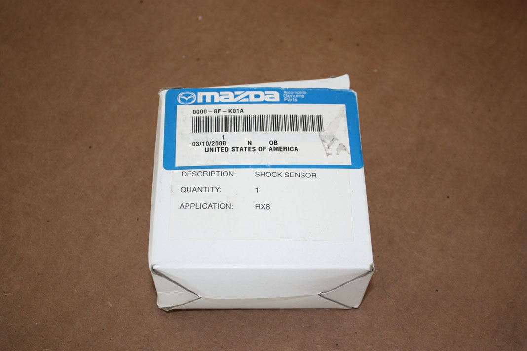
The part number for this product is 0000-8F-K01A, and the best price on the web at the time of writing this thread can be found at www.finishlineperformance.com
The Packaging that the product comes in
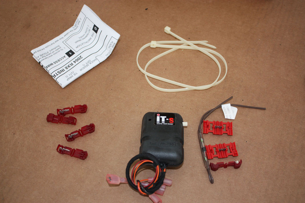
What is included in the package
[In progress]
The part number for this product is 0000-8F-K01A, and the best price on the web at the time of writing this thread can be found at www.finishlineperformance.com
The Packaging that the product comes in
What is included in the package
[In progress]
Last edited by paimon.soror; 04-15-2011 at 08:13 PM.
 04-15-2011, 08:06 PM
#2
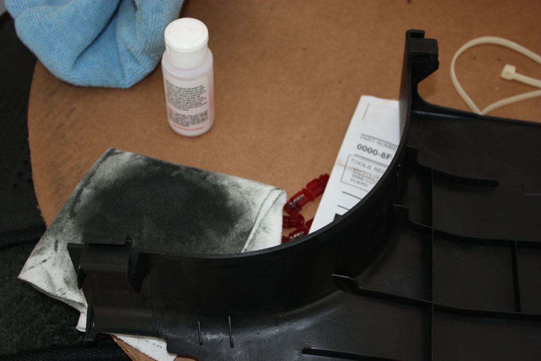
The first step is to get clear the passenger side of your car to work in. Removing the floor mats is recommended so you can easily access the kick panel. The next thing you want to do, is to pull up on the front of side panel that runs along the door frame. The reason you want to do this is because part of the kick panel runs underneath this.
[image to come]
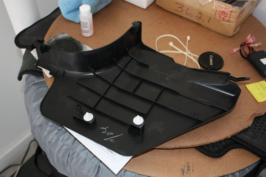
Next, remove the kick panel by pulling out the rear first. Do not try to remove from the front (the part closest to the seat), as there are tabs that may break. Work your way from the rear of the panel, to the front of the panel along the bottom. There are two plastic snap on clips, and two tabs. The image below shows what the kick panel looks like from the inside
Here is the clip that is at the rear (towards the front of the car) of the kick panel. This needs to be pulled out first to remove the rest of the panel
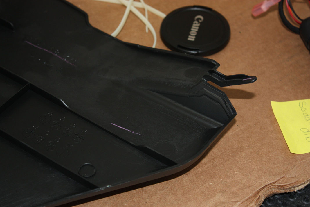
Here are the two clips that you want to beware of
[image to come]
Next, remove the kick panel by pulling out the rear first. Do not try to remove from the front (the part closest to the seat), as there are tabs that may break. Work your way from the rear of the panel, to the front of the panel along the bottom. There are two plastic snap on clips, and two tabs. The image below shows what the kick panel looks like from the inside
Here is the clip that is at the rear (towards the front of the car) of the kick panel. This needs to be pulled out first to remove the rest of the panel
Here are the two clips that you want to beware of
Last edited by paimon.soror; 04-15-2011 at 08:19 PM.
04-15-2011, 08:07 PM
#3
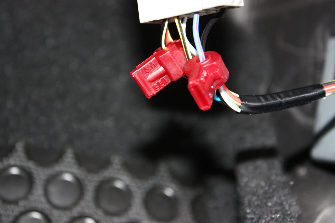
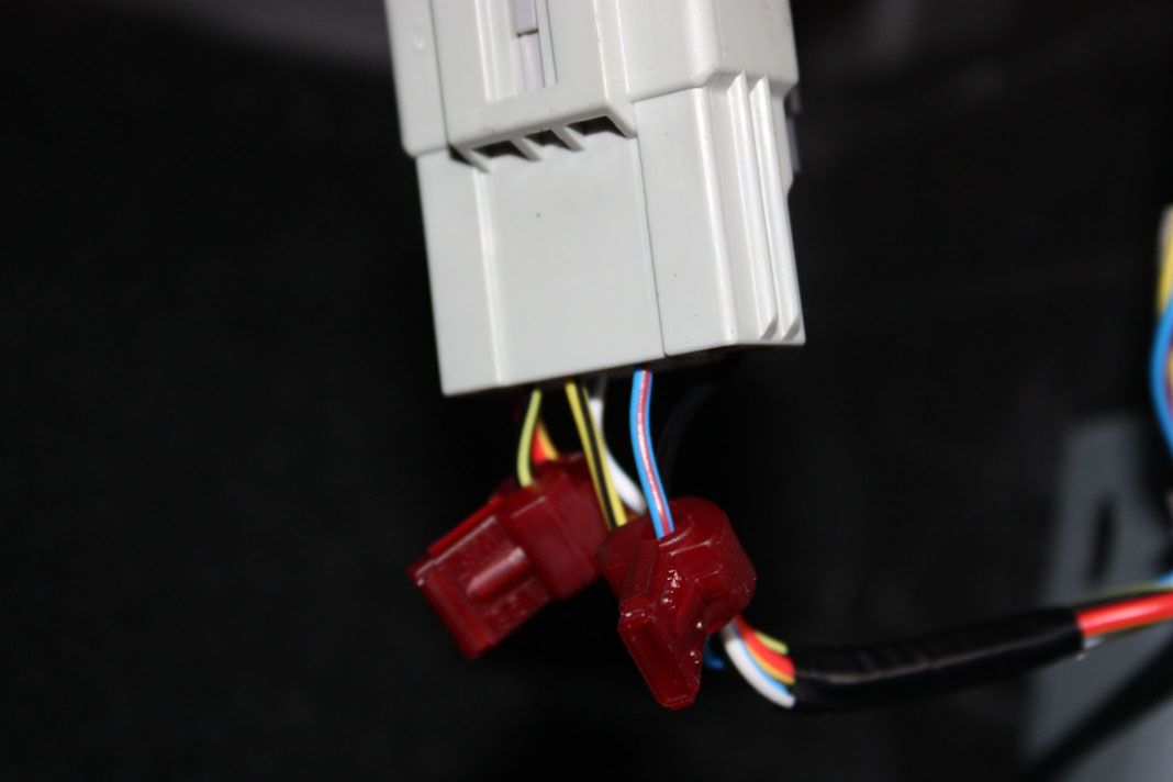
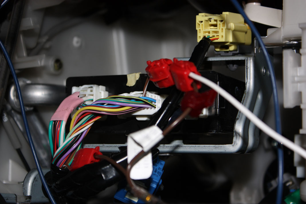
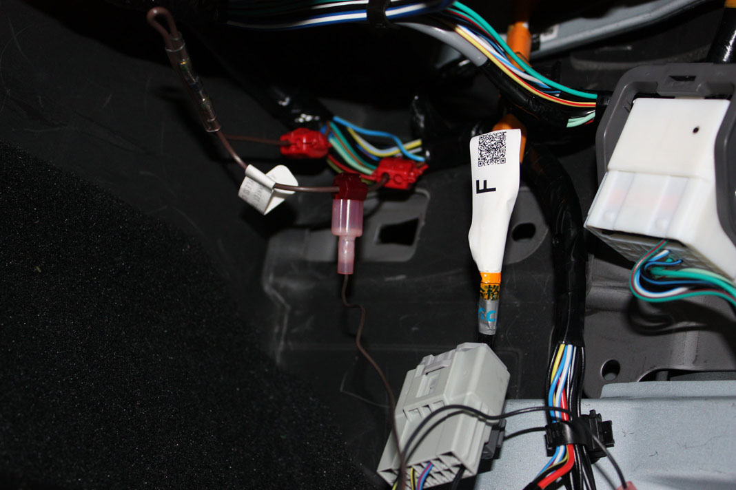
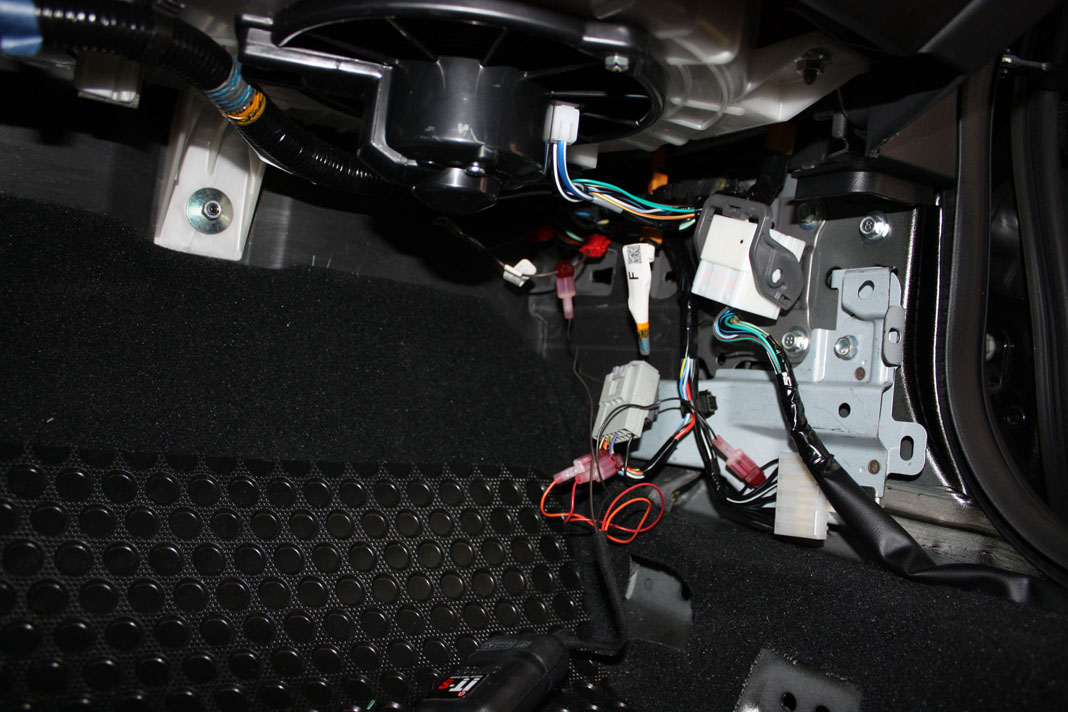
Next, you will notice three connecting harnesses that sit behind the kick panel. The one at the bottom left is the one we will primarily be working with, and the one on the bottom right is where our ground will go. The larger harness near the top will not be used in this installation.
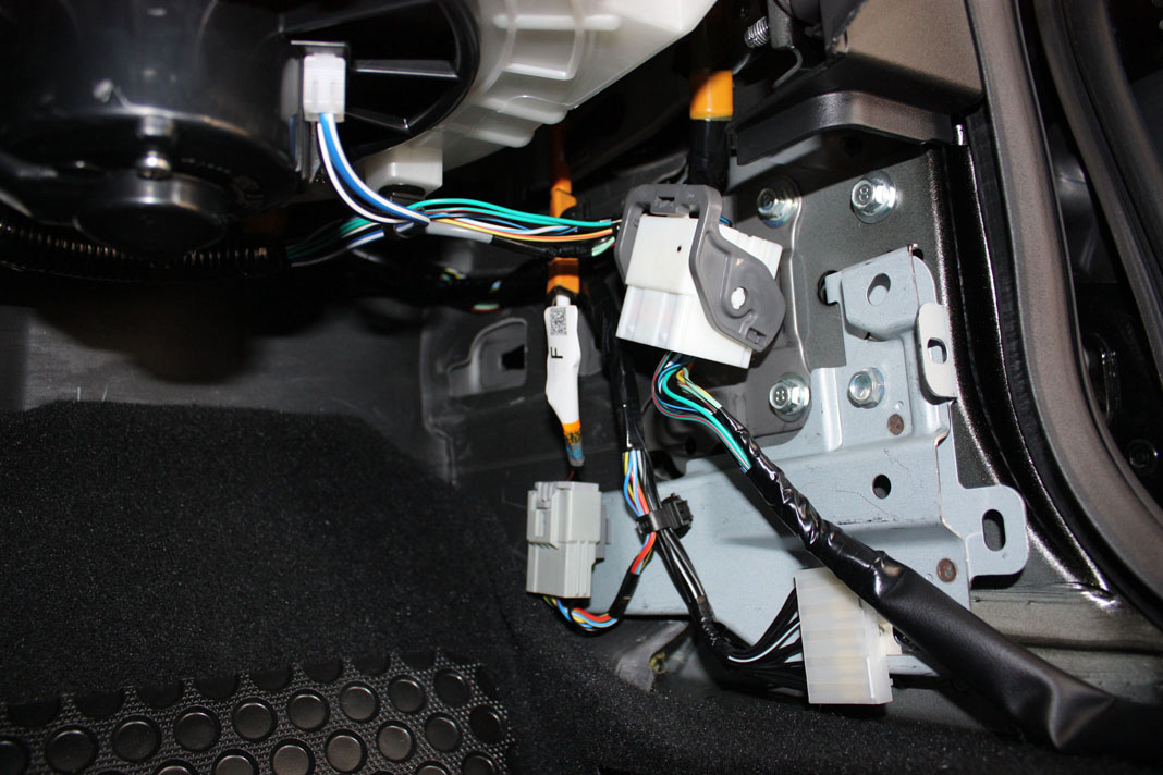
To make working with the primary harness easier, you can easily unclip it from the metal frame by sticking a finger behind, and pushing outwards. These harnesses are clipped in with very weak clips, so it shouldn't take much effort to remove.
There are two wires on this harness that we need to focus on, the BLACK with YELLOW STRIPE and the BLUE with RED STRIPE. For reference, these are found on the top row, pins 2 and 5 from the left.
Last edited by paimon.soror; 04-15-2011 at 08:23 PM.
04-15-2011, 08:07 PM
#4
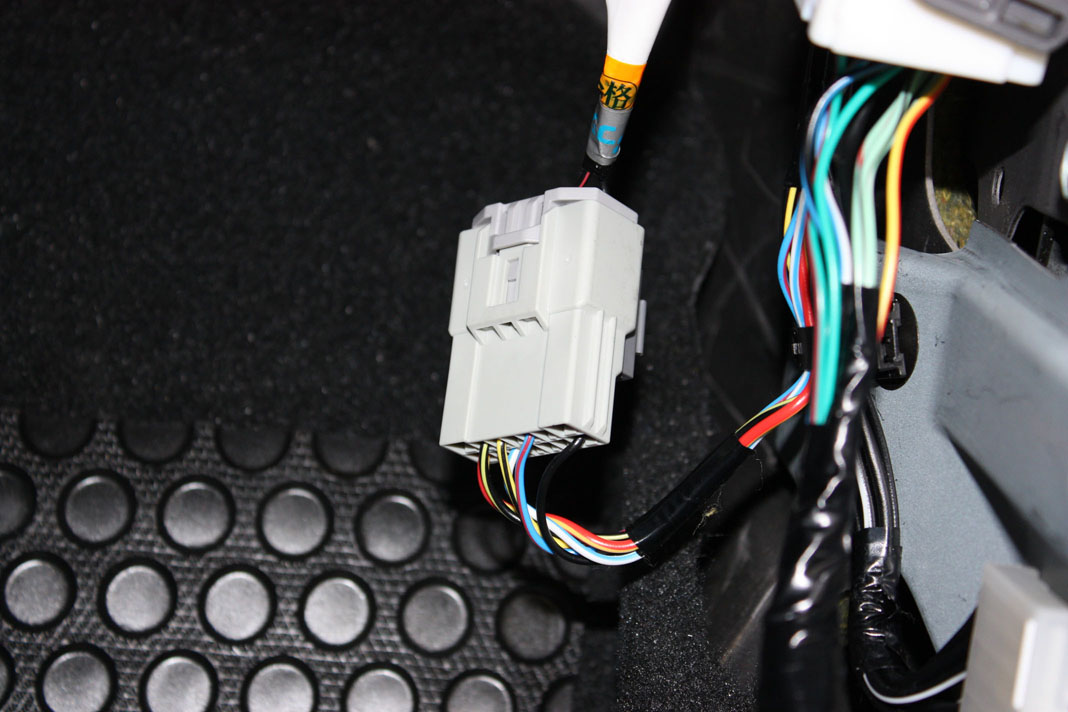
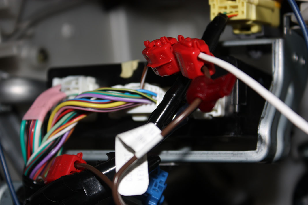
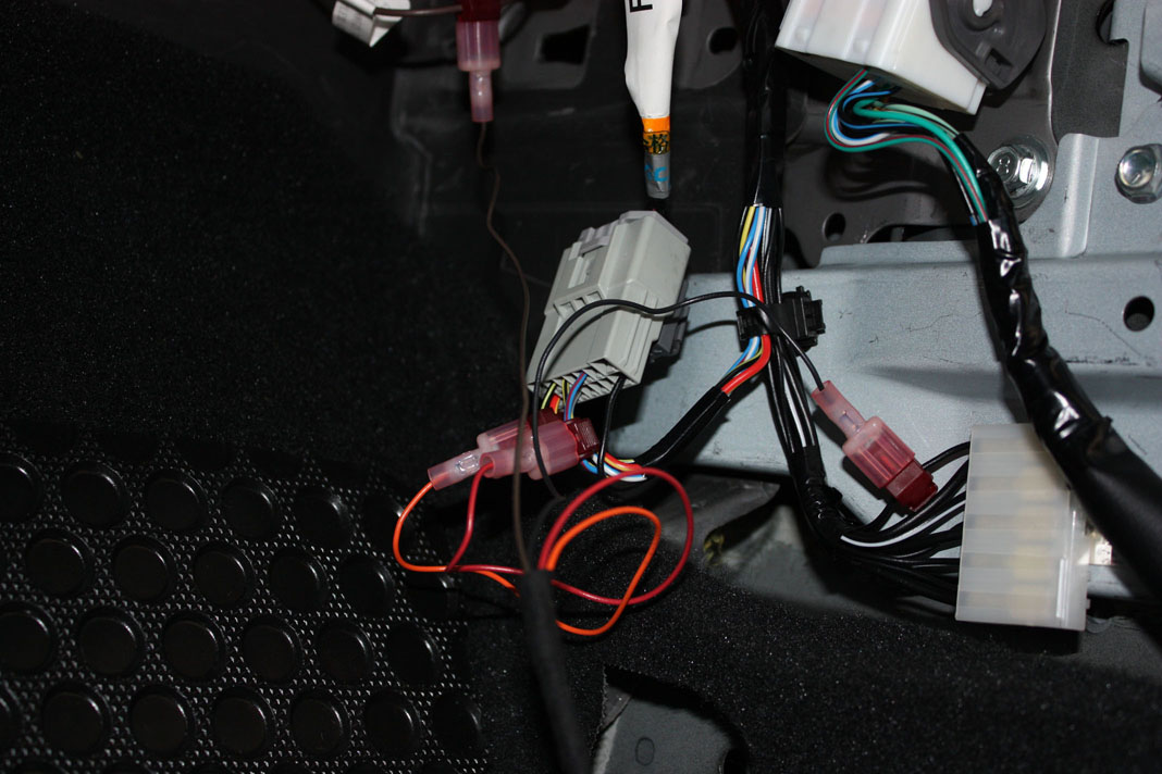
Take the supplied wire taps, and connect one to each of the wires mentioned in the last post. I found it easy to support the clip with one hand, while crimping it shut with a set of pliers with the other hand. Unfortunately the wires are a tad bit too thick, and the taps are too dull to do this by hand
Here is an alternate view of the harness with the taps installed
Here is an alternate view of the harness with the taps installed
Last edited by paimon.soror; 04-15-2011 at 08:26 PM.
04-15-2011, 08:08 PM
#5
The next thing we need to do is to prepare the trunk trigger diode. The kit comes with a wire that has a diode pre-installed. All we need to do is to prepare the wire by installing the large butterfly taps to each end.
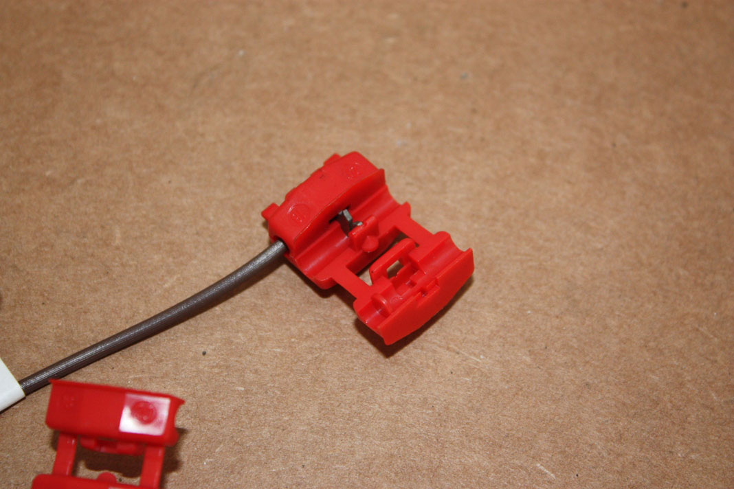
What you want to do is to take the butterfly tap, and locate the end WITHOUT the stopper, this is the end that will go to the supplied diode wire. The other side we want to make sure that the open end is facing away from the diode. In the picture above, take note of the orientation of the open wing of the tap, notice where the open (longer, unblocked) end is facing, this is very important.
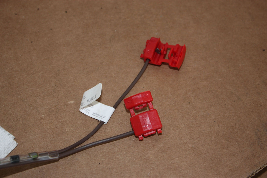
This should be the final result of preparing our wire
What you want to do is to take the butterfly tap, and locate the end WITHOUT the stopper, this is the end that will go to the supplied diode wire. The other side we want to make sure that the open end is facing away from the diode. In the picture above, take note of the orientation of the open wing of the tap, notice where the open (longer, unblocked) end is facing, this is very important.
This should be the final result of preparing our wire
Last edited by paimon.soror; 04-15-2011 at 08:30 PM.
04-15-2011, 08:08 PM
#6
The next part really took me a while since the instructions weren't very informative, and any DIY i found online pointed to an older gen RX8 which has a different harness setup behind the kick panel.
FOR SERIES 2 / TWO / DOS ONLY!!!!
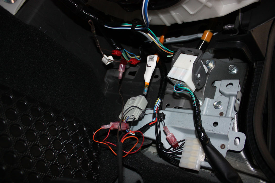
What we need to locate is the brown/white trunk light trigger wire. This is NOT in any of the three harnesses displayed earlier in this thread. Instead, it is located at the keyless entry module.
You will need to remove the glove box for this, and behind there, you will see the keyless entry module with three harnesses connected to it. The harness in the middle is the one we want to find the wire in. Along the top row, at the far right, you should find the brown/white wire. Snip that wire.
IMPORTANT
Next, take the brown wire assembly that we made earlier, and make sure that the flag side is connected to the brown wire coming from the keyless entry module, while the non flag side is going back down away from the keyless entry module. This is very important, if you mess this part up, you will damage the shock sensor
Note, you will realize that by placing this wire here, the original harness may not reach, you can improvise here by taking some standard 18gauge wire and tapping the label side and running it down the passenger kick panel.
FOR SERIES 2 / TWO / DOS ONLY!!!!
What we need to locate is the brown/white trunk light trigger wire. This is NOT in any of the three harnesses displayed earlier in this thread. Instead, it is located at the keyless entry module.
You will need to remove the glove box for this, and behind there, you will see the keyless entry module with three harnesses connected to it. The harness in the middle is the one we want to find the wire in. Along the top row, at the far right, you should find the brown/white wire. Snip that wire.
IMPORTANT
Next, take the brown wire assembly that we made earlier, and make sure that the flag side is connected to the brown wire coming from the keyless entry module, while the non flag side is going back down away from the keyless entry module. This is very important, if you mess this part up, you will damage the shock sensor
Note, you will realize that by placing this wire here, the original harness may not reach, you can improvise here by taking some standard 18gauge wire and tapping the label side and running it down the passenger kick panel.
Last edited by paimon.soror; 04-27-2011 at 05:32 PM.
04-15-2011, 08:09 PM
#7
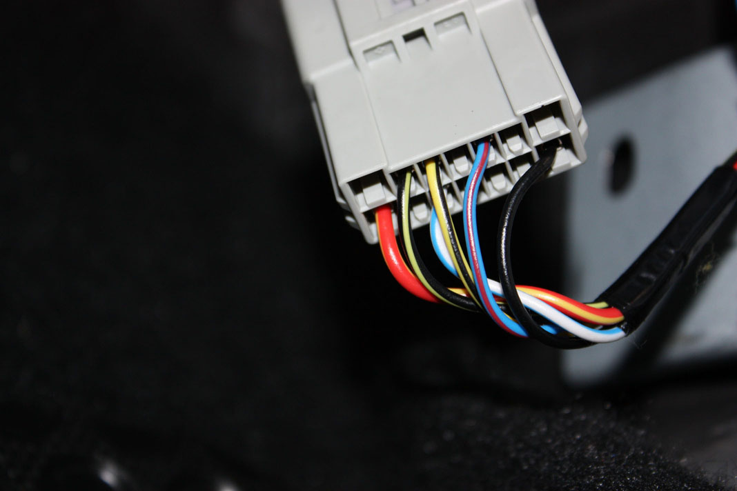
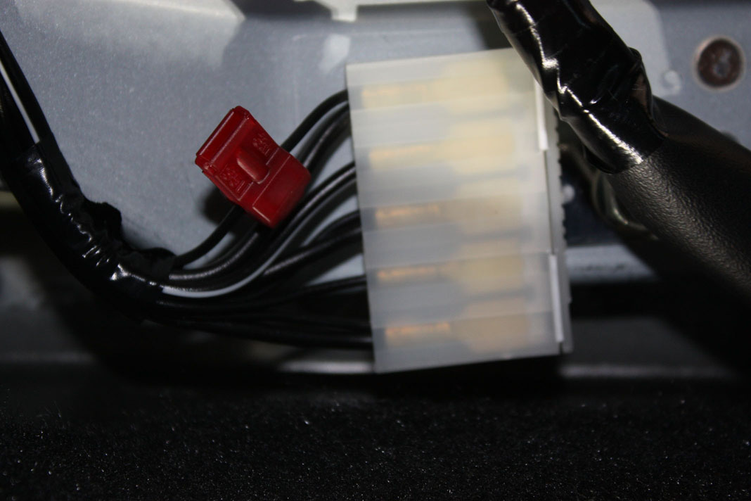
The final wire that we need to tap into is a ground. The harness connector that is at the bottom right of the three that was displayed in the second posting in this thread is full of grounding wires. Feel free to use any of the SOLID BLACK ONLY wires. There is one wire in this bundle that has a stripe on it, make sure you do NOT use that one.
Last edited by paimon.soror; 04-15-2011 at 08:56 PM.
04-15-2011, 08:10 PM
#8
Now that all of our wires have been tapped into, we can connect the shock sensor harness up. The wiring is as follows:
[Shock sensor Harness] ----- > [Vehicle Wire]
Red Wire ----- > BLUE/RED Wire
Orange Wire ----- > BLACK/YELLOW Wire
Brown Wire ----- > Diode Assembly Brown Wire (label side)
Black Wire ----- > Black Wire
[Shock sensor Harness] ----- > [Vehicle Wire]
Red Wire ----- > BLUE/RED Wire
Orange Wire ----- > BLACK/YELLOW Wire
Brown Wire ----- > Diode Assembly Brown Wire (label side)
Black Wire ----- > Black Wire
Last edited by paimon.soror; 04-16-2011 at 07:58 AM.
04-15-2011, 08:11 PM
#9
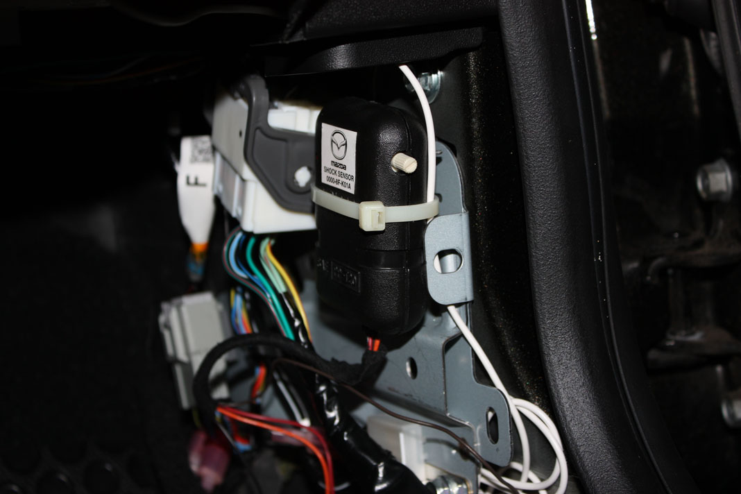
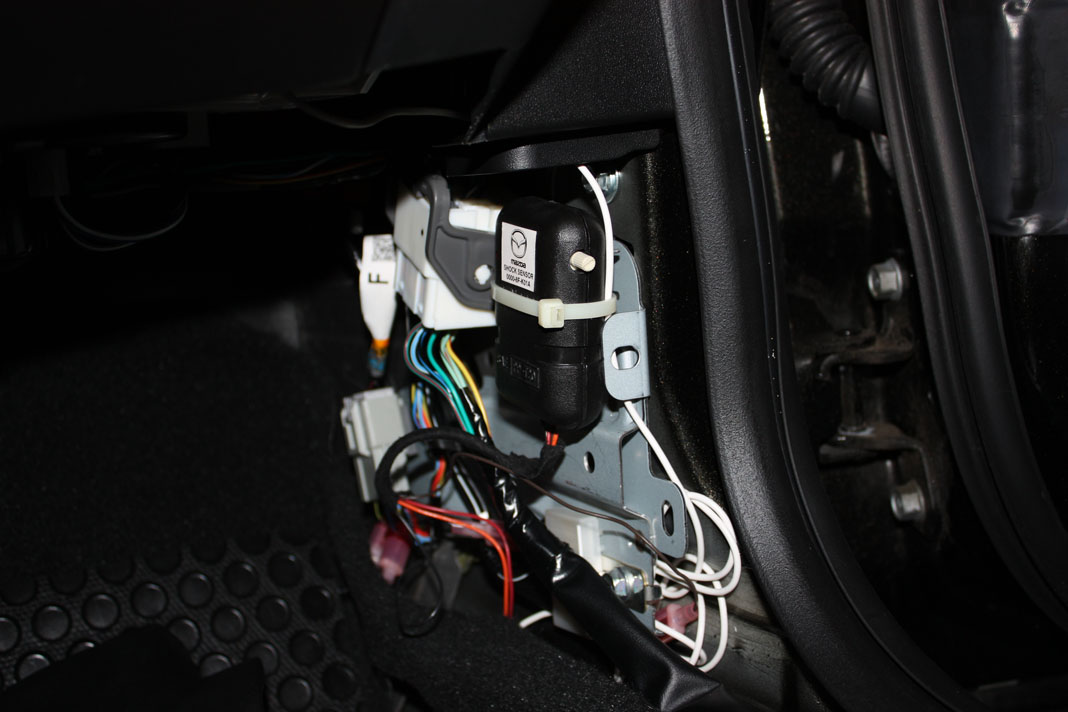
Now that the wires are connected, we are ready to test the sensor. First thing we want to do, is to turn the adjustment **** all the way counter clock wise. This is the Least Sensitive setting. Next, using the zip ties provided, tie the shock sensor to the bundle of wires that runs between the two connectors. Make sure that you orient the sensor in such a direction that you can easily access the adjustment ****. Do not worry about shock sensor orientation, it will not impact it's performance.
Next, close all of the doors, and lock the car with the keyless entry remote. Press lock twice to arm the system. Now, the car should not sound on any light impact, this is very important as you dont want you alarm going off whenever a car drives by. The security system should only trigger on heavy impact to the vehicle.
The instructions recommend testing the shock sensor by bouncing a tennis ball off of the windshield. If the alarm triggers, it should be turned down a notch and retested until it does not trigger when the tennis ball ricochets off. An alternative test is to just open palm slap the windshield.
IMPORTANT: If the alarm is not triggering no matter what sensitivity setting you choose, then you may have installed the diode assembly backwards. If this occurs, you need to replace the shock sensor after correcting the connection.
Once you have confirmed that your system works, you can neatly bundle up the wiring, and reinstall the kick panel.
I hope this DIY was useful!
Last edited by paimon.soror; 04-27-2011 at 05:30 PM.
04-16-2011, 09:44 PM
#10
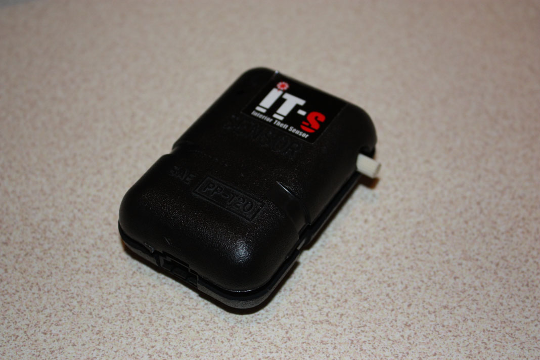
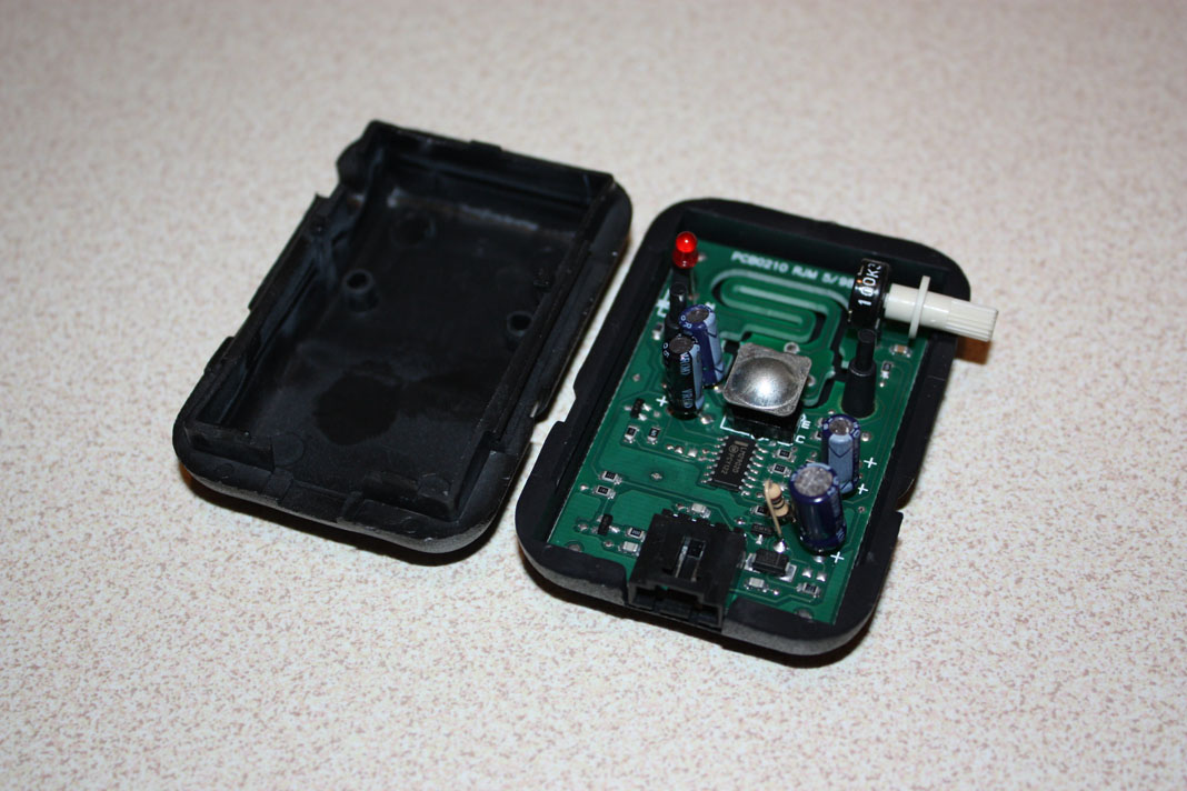
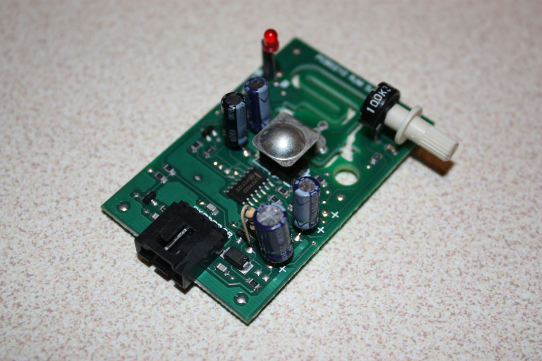
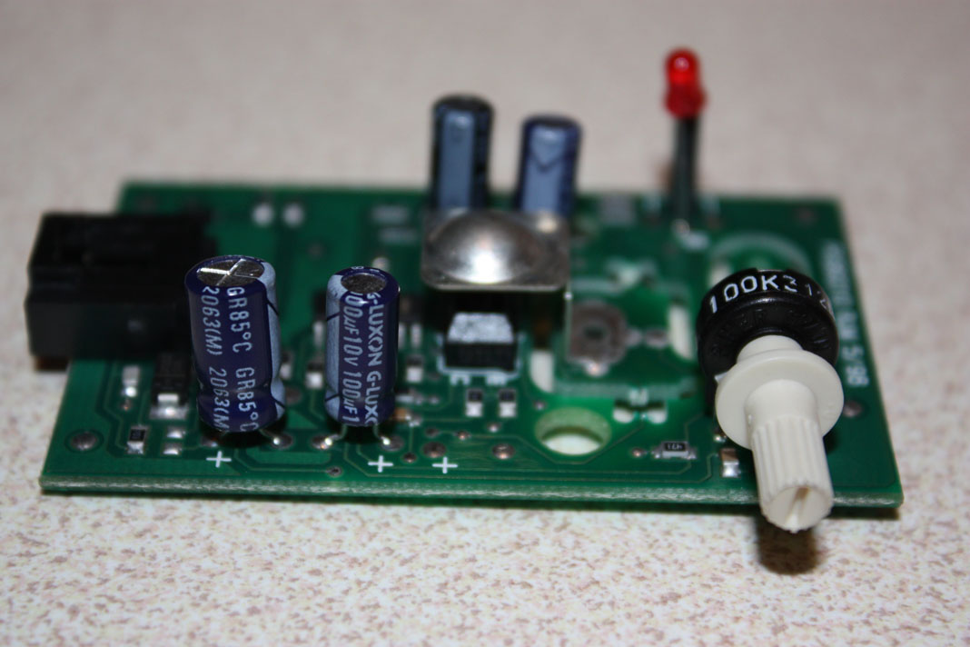
[PCB Board Reference Shots]
Board features the following:
Board features the following:
- A range of surface mount resistors, capacitors and transistors
- Main logic circuit is controlled by an LM2902D Amplifier
- 1 x 220uF capacitor (electrolytic)
- 1 x 100uF capacitor (electrolytic)
- 1 x 10uF capacitor (electrolytic)
- 1 x 4.7uF capacitor (electrolytic)
- 100K Potentiometer
- 1 x infrared/photoelectric diode
- 1 x red led
04-27-2011, 05:59 PM
#12

No problem. On your next go around, we could probably just do all the wires at the keyless control module behind the glove box.
Also remember everyone that Mazda says this cannot be installed on RX-8s with the advanced keyless system/key cards.
Also remember everyone that Mazda says this cannot be installed on RX-8s with the advanced keyless system/key cards.
04-28-2011, 06:31 AM
#13
Yup, noted that in the first post  also remember that the wiring outlined here is for the S2 ONLY.
Only difference between S2 and S1 is that the S2 (as you helped me with) uses a Brown/White wire for the trunk light feedback, while the S1 uses a solid brown.
also remember that the wiring outlined here is for the S2 ONLY.Only difference between S2 and S1 is that the S2 (as you helped me with) uses a Brown/White wire for the trunk light feedback, while the S1 uses a solid brown.

 04-28-2011, 06:10 PM
#16
Recreational User
iTrader: (1)
Join Date: Feb 2010
Location: Austin, TX
Posts: 363
Likes: 0
Received 0 Likes
on
0 Posts
FYI, I'm not looking for an answer for why it won't work on the adv. system. Just ranting... Waaa
Also, on that site I can't believe they charge $149.95 for a stock, black, shift ****! Insane!
:::: Putting stock **** in fire safe :::
Also, on that site I can't believe they charge $149.95 for a stock, black, shift ****! Insane!
:::: Putting stock **** in fire safe :::
 04-29-2011, 09:04 AM
#20
Looking at the wiring diagram, I don't see why it would not work. Someone with advanced keyless will have to either install one and report or perhaps test the system out electrically.
If someone with advanced keyless wants to test it, let me know and I'll try to write the steps you will need to perform.
If someone with advanced keyless wants to test it, let me know and I'll try to write the steps you will need to perform.
04-29-2011, 09:20 AM
#21
Looking at the wiring diagram, I don't see why it would not work. Someone with advanced keyless will have to either install one and report or perhaps test the system out electrically.
If someone with advanced keyless wants to test it, let me know and I'll try to write the steps you will need to perform.
If someone with advanced keyless wants to test it, let me know and I'll try to write the steps you will need to perform.
 05-05-2011, 07:19 AM
#25
haha I tried to be very discreet about it
Btw: So far so good on the sensor. Had some thunderstorms and whatnot, no misfires on the alarm. Sensitive enough that if i bump into my car (or rock it) it goes off, but so far no false alarms.
Btw: So far so good on the sensor. Had some thunderstorms and whatnot, no misfires on the alarm. Sensitive enough that if i bump into my car (or rock it) it goes off, but so far no false alarms.