CAS and Spark Plug Clearance
 02-01-2006, 02:57 PM
#1
Spinning Dorito Junkie
Thread Starter
iTrader: (2)

Join Date: Jul 2003
Location: Halifax, Nova Scotia, Canada
Posts: 747
Likes: 0
Received 1 Like
on
1 Post
CAS and Spark Plug Clearance
A racing/track day buddy of mine (Honda guy, but he's all right) is also an engineer and came up with a little project.
It's a simple and inexpensive box specifically for testing compression and general health of a rotary.
You install a sensor into one spark plug hole, another lead on the CAS, turn the car over a few times and it outputs it all to your PC with pretty graphs and charts to show you the condition on the engine. (I'm sure there is more, but he's an engineer, I'm a sales guy...)
Anyway, he's run it on a volunteer RX-7, and now wants to try an RX-8.
So, he's asked me a few questions that I'm not sure of just to make sure he's got all the bits he needs.
1) Are there any spark-plug clearance issues particular to the Renesis?
2) Any idea what/where the CAS is and looks like on this car? I don't have a shop manual and my car is kind of in storage at the moment so I can't go look.
Apparently it will do some of the tests without the CAS hooked up, but you won't be able to tell where in the chamber the poor compression (for example) is.
Any other aspects particular to the Renesis implementation that we aren't thinking of?

 02-01-2006, 05:02 PM
#3
Spinning Dorito Junkie
Thread Starter
iTrader: (2)
Join Date: Jul 2003
Location: Halifax, Nova Scotia, Canada
Posts: 747
Likes: 0
Received 1 Like
on
1 Post
Crank Angle Sensor
I think it does do both rotors. I haven't seen the thing yet... he lives about 5 hours away from me.
Like I said, he's the engineer, I'm just a stupid sales guy.
It is basically just a rotary compression testor, but I guess the thing here is it's really cheap and simple to use, plus makes pretty graphs.

 02-01-2006, 06:19 PM
#7
Administrator

.
Originally Posted by StealthTL
The sensor has two wires, and at connector B1.27 they are Y/R & Y/B.
Originally Posted by rotarygod
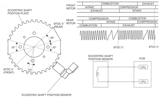
Yes that picture above shows the exat sinewave that an o-scope should show as the wheel turns. The wheel is not a 60-1 or 60-2. The most common wheels out there are 36-1 or 36-2 wheels. The RX-8 wheel is a 36-2-2-2. Look at the above picture to see how this works. Notice that each individual tooth is 10 degrees apart center to center. Since we only have 360 degrees in a full circle, we divide that number by the degrees of separation to arrive at 36 base number of teeth. However we see that there are flat spots. Notice that in the middle of these flat spots is what looks like the top of a tooth. It is. Also note that the teeth at the ends of these flat spots are exactly 30 degrees apart. Each tooth is measured from the center of the tooth to the center of the next. Since at least 5 degrees per side is going into the gap between the teeth, that leaves us with 20 usable degrees left in this large flat area. This means that we are missing 2 teeth per flat side. This shows up as the -2. There are 3 sides like this. -2-2-2. 36 base teeth, 3 gaps of -2 teeth = 36-2-2-2. Currently only the stock ecu or a Motececu can read this pattern as it is unique in the automotive world.
The ecu code is written to read these large areas without usable teeth but it also reads the number of teeth between these gaps. This is how it knows how to time the engine and also how to verify which rotor it is firing at. This whole sequence is only used to determine where top dead center is or more appropriately 5 degrees btdc is for both the front and rear rotor. That's all the trigger wheel does. The ecu uses this base as a starting point for which to start adjusting timing either advanced or retarded. If there is any problem with the way that the ecu sees the pattern of the teeth, the car will not run. It can't as the ecu is no longer getting the correct signal. Any problems would be located in the software and not with the wheel.
The ecu code is written to read these large areas without usable teeth but it also reads the number of teeth between these gaps. This is how it knows how to time the engine and also how to verify which rotor it is firing at. This whole sequence is only used to determine where top dead center is or more appropriately 5 degrees btdc is for both the front and rear rotor. That's all the trigger wheel does. The ecu uses this base as a starting point for which to start adjusting timing either advanced or retarded. If there is any problem with the way that the ecu sees the pattern of the teeth, the car will not run. It can't as the ecu is no longer getting the correct signal. Any problems would be located in the software and not with the wheel.
 02-01-2006, 07:27 PM
#10
Registered

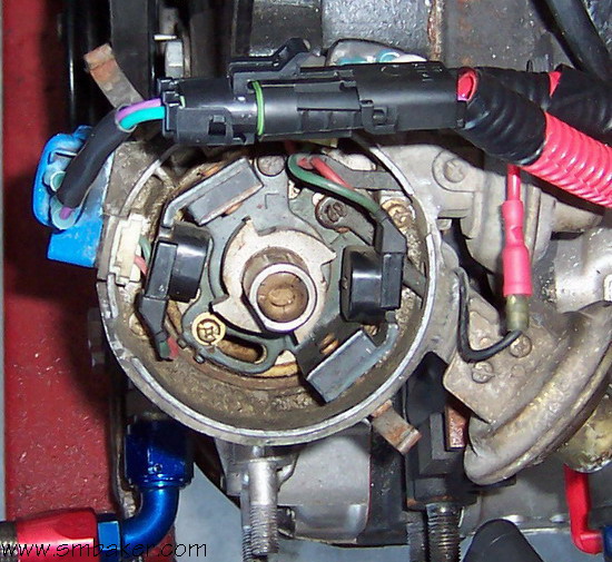
That picture above is a 1st gen RX-7 distributer with the cap and rotor removed. As you can see it has 2 sensors and 4 evenly spaced teeth. The blue object to the left is the leading J109 ignitor. The trailing ignitor is 90 degrees around the distributer hidden from view by the plug at the top of the picture. The top picture is a 2nd gen cas. The 2nd generation RX-7 uses a crank angle sensor that installs in the same spot as the distributer. They both install into the top driver's side of the front cover. Inside the 2nd gen cas, you have 2 wheels. One has 2 teeth and the other has 24 teeth. The leading gets it's signal from the 24 tooth wheel and the trailing gets it's from the 2 tooth wheel. Both the distributer and the cas spin at half of the engine's rotation. The cas 2 tooth wheel has the teeth spaced out so that their signal arrives in between 2 of the larger wheels. The ecu interprets this as a 12+1 wheel. The 3rd gen RX-7 used a different setup with the sensor on the crank. There were 2 sensors on the front cover itself and 2 teeth on the trigger wheel. The RX-8 is different still. Like the 3rd gen RX-7 it has a sensor on the front cover but only 1. It's wheel as shown above is unique and is seen by the ecu as a 36-2-2-2. If the device your friend made is designed to work with a cas, it will only work on 2nd gen RX-7's and that's it. It definitely will not work on the RX-8.
02-02-2006, 07:55 AM
#11
02-02-2006, 08:56 AM
#12
Registered User

Join Date: Feb 2006
Posts: 5
Likes: 0
Received 0 Likes
on
0 Posts
Hi Guys;
Pardon my ignorance of all things rotary, I'm a Honda guy - don't shoot me. School me instead.
The device is indeed a rotary compression tester.. it's a small board that connects to a PC or Palm. I've tested it on a RX7 with the dual-wheel configuration CAS. I'd love to see if something could be made to work with an RX8.
Obviously, the system for determining angle is different on an RX8. You could just graph the engine compression over time and get something sinusoidal that will give you a picture of the health of the engine. It'd be slicker to relate that to angle.
It's not important that the systems are numerically different; the firmware is trivially adjusted. The bigger questions are the physical type of sensors, and if they're on a easily accessed harness.
My question is;
- Is there a system for determining rotation angle on the RX8 that's easily tapped? The RX7 had a convienent plug you could disconnect and put clips onto.
- Does that system use magnetic relucatance style sensors?
- If not, what type of sensor does it use, so I can build that onto the board.
02-02-2006, 01:02 PM
#16
Registered
Originally Posted by xtal
Well, not exactly RPM - looking for a signal that denotes where in the combustion cycle the crank is, to use piston lingo. (crank angle sensor)
02-02-2006, 05:00 PM
#17
Registered User
Join Date: Feb 2006
Posts: 5
Likes: 0
Received 0 Likes
on
0 Posts
Feed sensor data, and a client application to intrepret and graph it.
Need to know if there's a way to get the information I need from the Rx8 sensors.
Rotarygod: Is that a magnetic reluctance style sensor (same as RX7, most CAS sensors use this style), and is it accessable on a connector without major dissassembly?
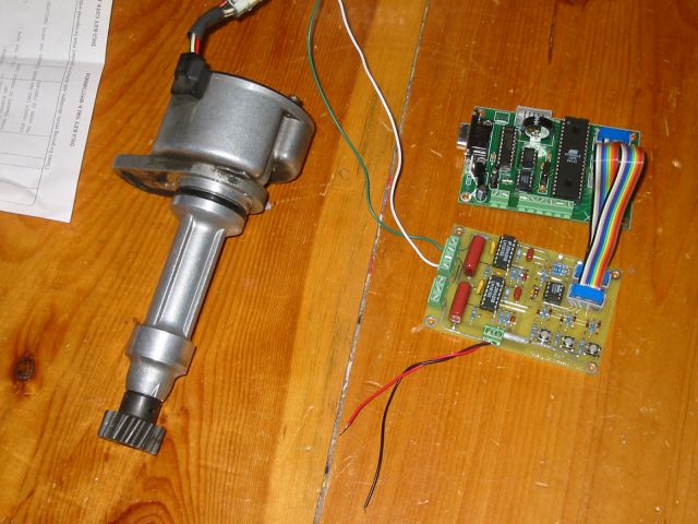
There's the RX7 setup.
Need to know if there's a way to get the information I need from the Rx8 sensors.
Rotarygod: Is that a magnetic reluctance style sensor (same as RX7, most CAS sensors use this style), and is it accessable on a connector without major dissassembly?
There's the RX7 setup.
Last edited by xtal; 02-02-2006 at 05:03 PM.

 02-04-2006, 10:01 AM
#22
Spinning Dorito Junkie
Thread Starter
iTrader: (2)
Join Date: Jul 2003
Location: Halifax, Nova Scotia, Canada
Posts: 747
Likes: 0
Received 1 Like
on
1 Post
Steve, sounds like your project might just work. We can set something up in the next few weeks to plug it into my car and see what happens if you like. (I just need some warning to clear a path through the garage to get to my car.)
If you keep this up, maybe we can get you to see the light and drop a 13B into that Formula Ford of yours....
If you keep this up, maybe we can get you to see the light and drop a 13B into that Formula Ford of yours....
03-02-2006, 10:17 AM
#23
Registered User
Join Date: Feb 2006
Posts: 5
Likes: 0
Received 0 Likes
on
0 Posts
Heh, redshift, there's a MR2 engine in my Flibre now. Hasn't been a ford for awhile. I'm going to build a F1000 chassis and probably use a CBR929 engine in it next. Although, I guess those little rotaries are small..
Anyway, the board is done, I just need to get to your place to test it out. I think the universal compression tester adapter kit I picked up will work perfect. $50, wish I found it before we blew through $100 worth of billet.
X
Anyway, the board is done, I just need to get to your place to test it out. I think the universal compression tester adapter kit I picked up will work perfect. $50, wish I found it before we blew through $100 worth of billet.
X

Thread
Thread Starter
Forum
Replies
Last Post