When you click on links to various merchants on this site and make a purchase, this can result in this site earning a commission. Affiliate programs and affiliations include, but are not limited to, the eBay Partner Network.
Hello everyone! So, this has been done for a while and I’ve been putting off writing this for months, but here we are! As we all know, nothing is ever truly done so stuff can be added/fixed in the future. Also feel free to point anything out or ask questions, I take criticism of all kinds (it’s how we learn).
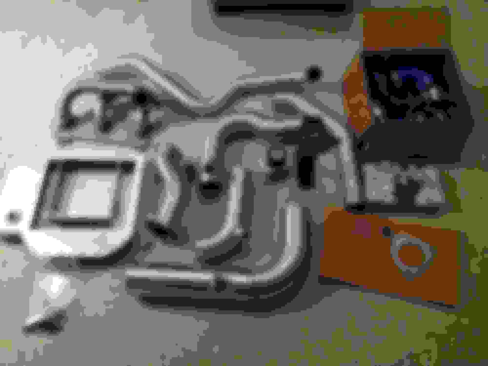
Anyway, let’s get jamming. Here's a quick break down of parts (note: this is not vendor endorsement, simply what I've chosen to buy and document here):
Turbokit: RX8Performance (RX8P) turbo kit which includes:
Precision 6266 CEA Turbo .82 A/R housing
Precision wastgate
Synchronic recirculated BOV
RX8P intercooler w/mounts
RX8P turbo manifold and downpipe
3" Flex joint
RX8P Charge pipes and couplers
Fuel: Deatsch werks 255lph fuel pump
clean injection 850cc/min injectors (funny story about these, no one knows the latency values.)
Uncapped reds 720cc/min injectors (because I know the latency’s.....)
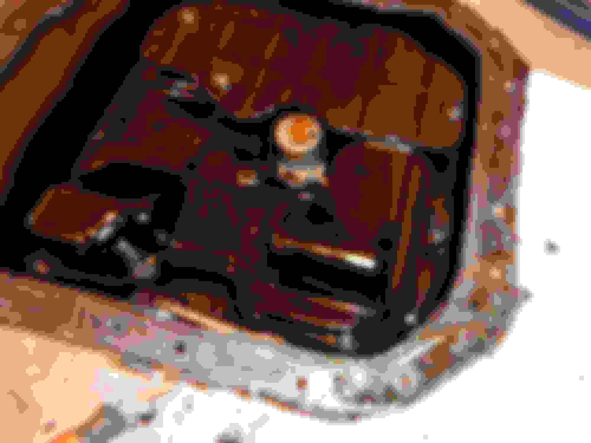
The first install I technically did was an injector swap. Initially I swapped the yellow primary 2’s into the primary 1 position and dropped in some 850cc Toyota injectors into the secondary and primary 2 slots but I couldn’t peg down the injector latencies, making tuning a nightmare. Inevitably I ended up opting for uncapped reds for the primary 2 and secondary injectors, which ended up being about 700 cc in Accesstuner. Once that nonsense was sorted out, I jacked up the car drained all the necessary fluids. Removing the oil pan is always fun because scraping off all the RTV makes me want to stick my face in a belt sander, but I got it off and all cleaned up. I bought an oil pan gasket and it was quite possibly the greatest purchase I’ve ever made, easy to install and no leaks at all. Stellar. Then I swapped over all the components of the old oil pan to Scott’s new one. No problem. To get the oil return line to fit, you can do one of three things: 1) get a 23/32” drill bit and a �” NPT thread tap and do it yourself 2) ask and see if Scott can put one in for you (he most likely can/will) 3) mark off where you want the hole and take it to a shop/friend that can do it for you. This is about where I put mine.
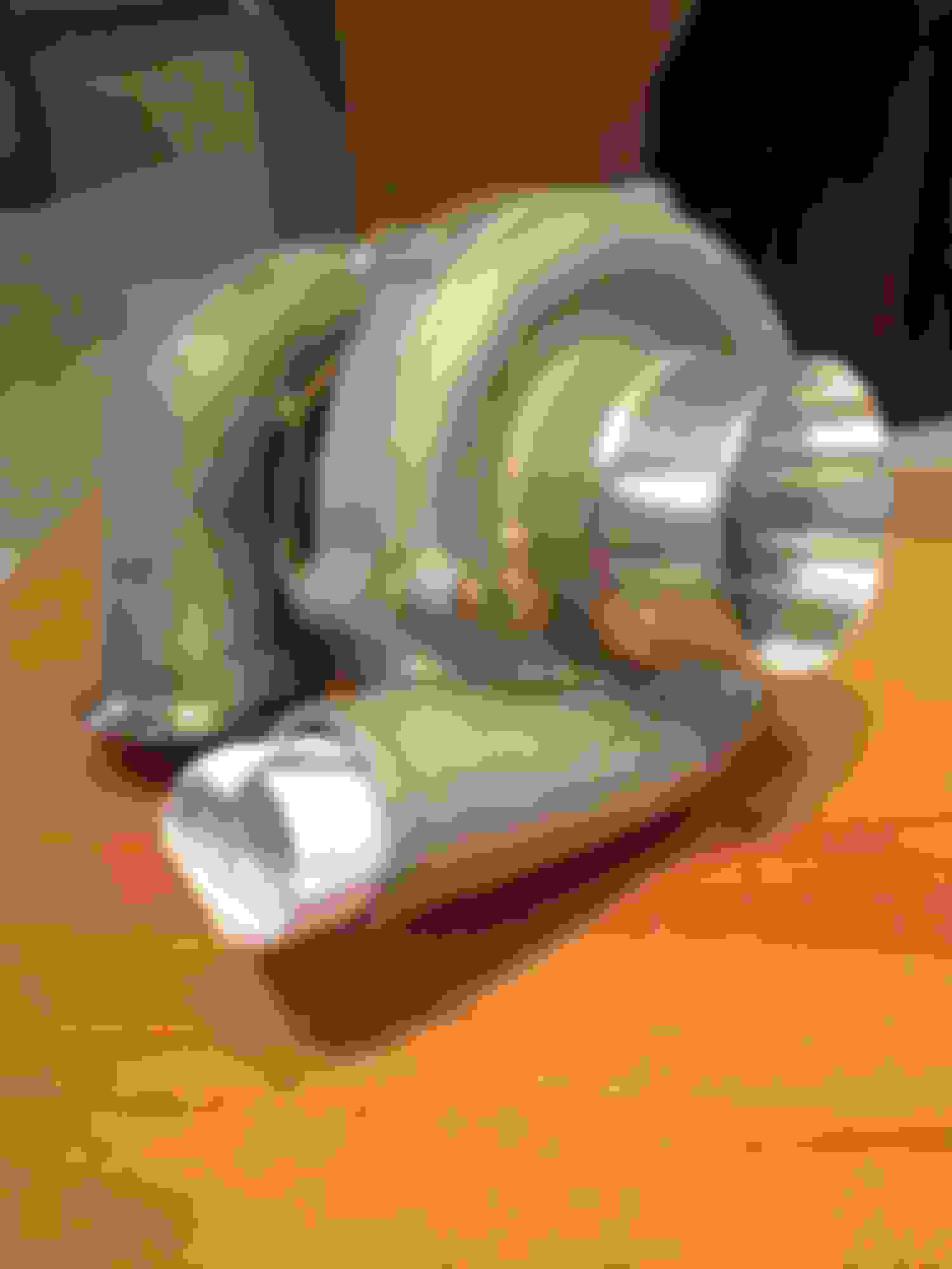
Tackling the next big ticket item: the turbo and manifold. Despite being something I thought was stupid simple, turned out to be slightly more tricky than anticipated. So by now I had completely taken out the intake box, battery, battery box, motor mounts, front cross brace, front chassis brace, midpipe and related braces. In order to get the turbo in, here’s what I had to do:
jack up the engine as high as it would comfortably go
take off the stock exhaust manifold
get a solid steel rod and a nice hammer, whack the crap out of the passenger footwell/firewall area so the turbo would actually fit between the chassis and the engine
take out the air pump in the engine bay and remove the stupid airline that attached to the old manifold (aint no one need that crap no more)
adjust the compressor outlet angle, slide the turbo in there and zip tie it to the side
fannegle the manifold in there, bolt that up, then attach turbo to the manifold.
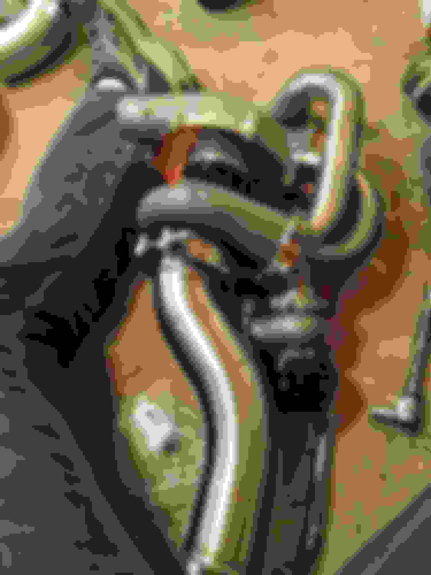
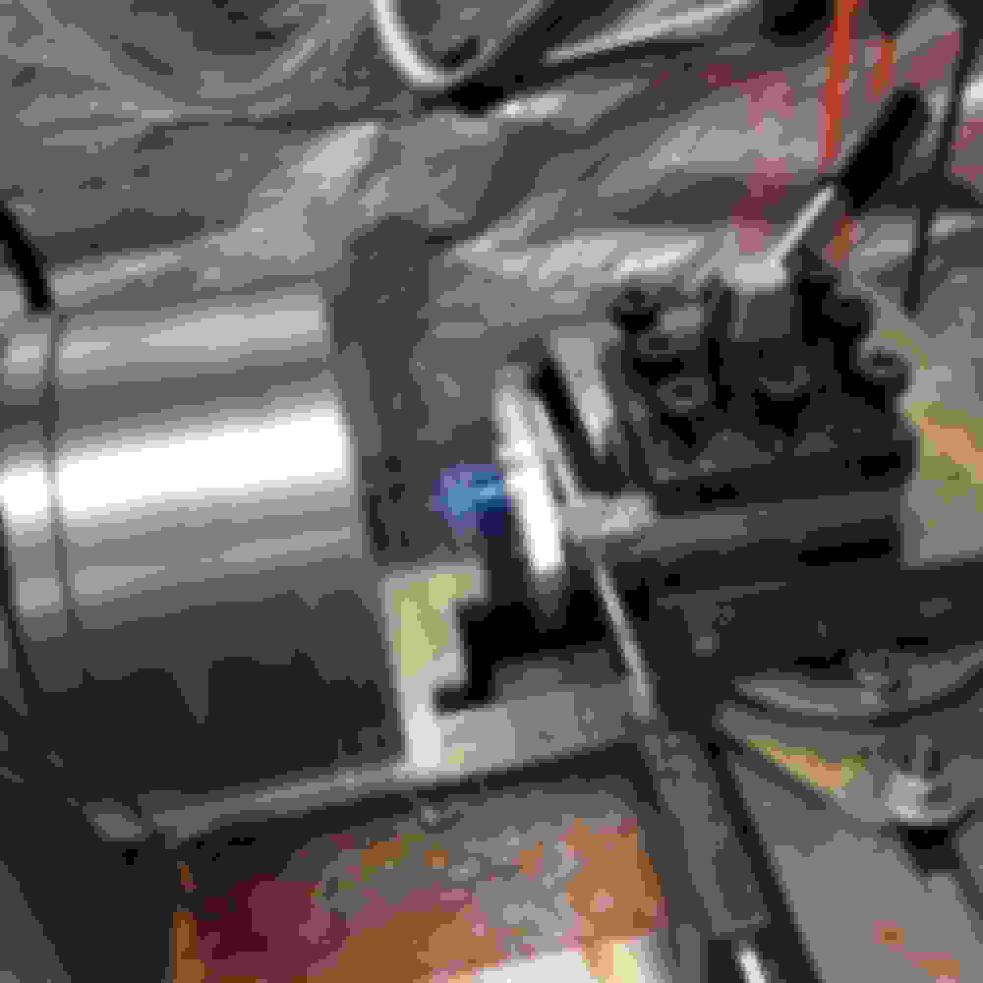
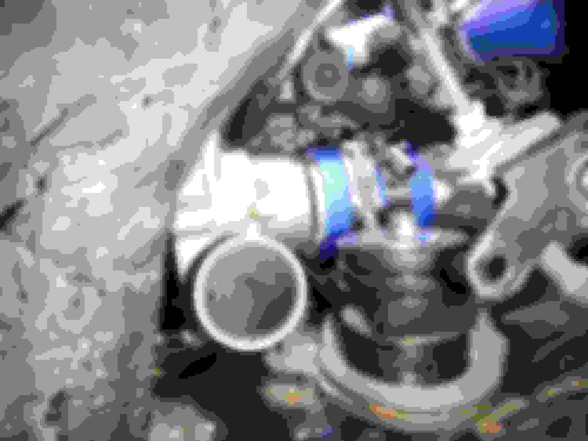
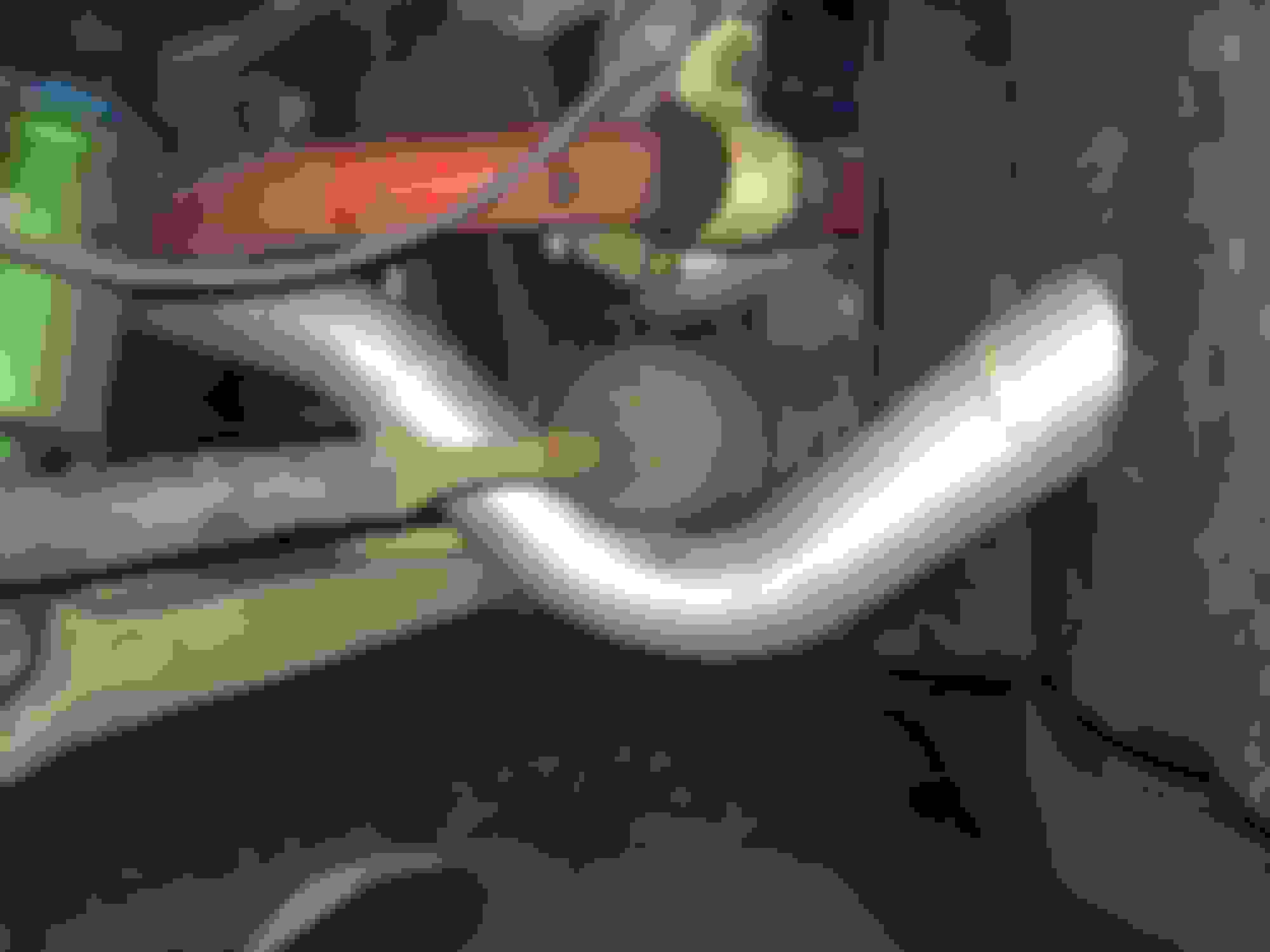
Easy right? Cause there’s no way the whole assembly is going in there as one piece. I also took this time to route the oil feed line from my sandwich adapter under my oil filter back behind everything to the turbo inlet. In retrospect, one of my few complaints about this kit is the oil feed and return lines. The included drain plate that bolts to the turbo was a tad too long and the hose bend angle was too large. The result was that the tip of the fitting hit the engine block and I couldn’t swing it out of the way in any configuration. So, I through the whole plate on my lathe and turned it down until it fit. The plate consists of an actual aluminum bracket that a �”npt to 10 AN adapter is threaded into the plate, then the hose goes into the 10AN side. Later on I ended up buying a plate that had the 10AN fitting machined into it and that worked with the original 45 degree bend fitting. The oil feed that goes into the turbo could have used a bend as opposed to the straight fitting as the straight fitting pushes the oil line right into the chassis and creates a sharp bend. When heated the line fatigues and will crack if removed after many heat cycles, resulting in more oil shooting everywhere then the Kuwaiti oil pipe lines in the Gulf War.
Now that I’ve gotten the turbo in, I decided to bolt up the waste gate and down pipe. Well the waste gate goes in without a hitch, but there was a minor issue with my downpipe, the O2 sensor bung was missing. To remedy the situation I called up Scott and explained what happened. He immediately created a shipping label and had me ship the pipe back to him where he got the bung welded in. Quite the expedient process I may add. Now, if there’s one thing I regret not doing while talking to Scott during the purchasing and order detail process, its having him install a SECOND O2 sensor bung in the downpipe for my aftermarket wideband AFR sensor. If you choose to go with this kit for your RX8, definitely ask Scott to put in a second O2 bung for your sensor!
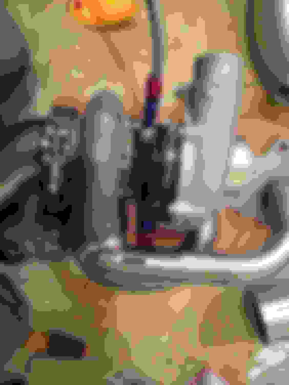
Installing the motor mounts is relatively easy. The driver side goes in as normal and the passenger side literally just sandwiches over the exhaust manifold. One issue I had with overall function was that the manifold ended up contacting the front sub frame and the turbo sounded like a space ship. All the time (albeit it sounded super cool, vibrations are really bad for spinning things). So to fix the problem I had to stack some �” washers under the motor mounts on both sides. On the passenger side, I put two under the black bar/on top of the existing washer to shim the motor slightly upward. I used the same number and type of washer on the driver side as well, also on top of the washer sitting atop the polyurethane mount. I also had to remove a bit of material off the left side of the passenger motor mount to get it to fit in the sheet metal guide frame. You can see the flat part of the mount siting right under the turbo outlet.
Now, that everything on the exhaust side is good to go, lets look at charge pipes and mounting the inter cooler. The biggest and easiest thing to get in place is the giant ace intercooler. The mount bolts right up to the hood latch bolts behind the crash bar. Speaking of crash bar, I did some modifications to it to get the intercooler to fit nicely. First up, I had to put washers between the crash bar and the chassis to insure there was physically room for the intercooler to exist. I’m not running the car without the bar so science must be done. Another modification to the crash bar was for airflow. Imagine the cross-section of the crash bar as a big rectangle with a partition in the middle. I simply cut off the lower portion of the rectangle before the partition so I had at least one full tube intact. Now the engineer inside me is crying at this point for destroying the structural integrity of a perfectly good chassis member but the mad scientist half demands progress with no compromise to performance. From what I’ve been told, some guys cut out the steel rectangle entirely and then weld chromoly tubing across the two crush towers. Something I noticed during MAF scaling during initial tuning was that there was no stable airflow. Ever. So I went back and looked at the intake right before the MAF. The honeycomb and 10” straight before the MAF should have taken care of most disturbances, but something was still screwy. The problem ended up being the silicone elbow that goes from the bumper area to the engine bay where the VFAD used to sit. Moreover, the intercooler mount was the real culprit. I’m not sure if I got a bunk mount but the horizontal bend was sitting too high causing the 90 degree elbow to squish between the intercooler mount on the bottom and the VFAD hole on the top. My only two guesses were that this squish caused one of the following: 1) it created a flow so turbulent it had an entry length longer than 10” or 2) the squish caused the max velocity of air flow to shift somewhere else in the circular cross section other than the centerline. Either way, things got messed up. So I cut off a long strip of the mount, rotated that 90 degrees, machined a spacer block, bolted that up, then cut away portions of the intercooler mount that squished the elbow. Since I was also using the FEED type bumper, I had to cut away bits near where the filter sat. Otherwise that would push up on the bumper and fitment was terrible. Not sure if you stock bumper guys will need to do that or not.
Now that the intercooler was mounted and manifold was installed, it was time to install all the charge pipes. You may want to sand off the TIG weld nubs from assembly to aid in better sealing of the charge pipes. I capped the ends of the pips with paper towels then used a sanding attachment on a cordless drill to clean off the nubs fairly easily.
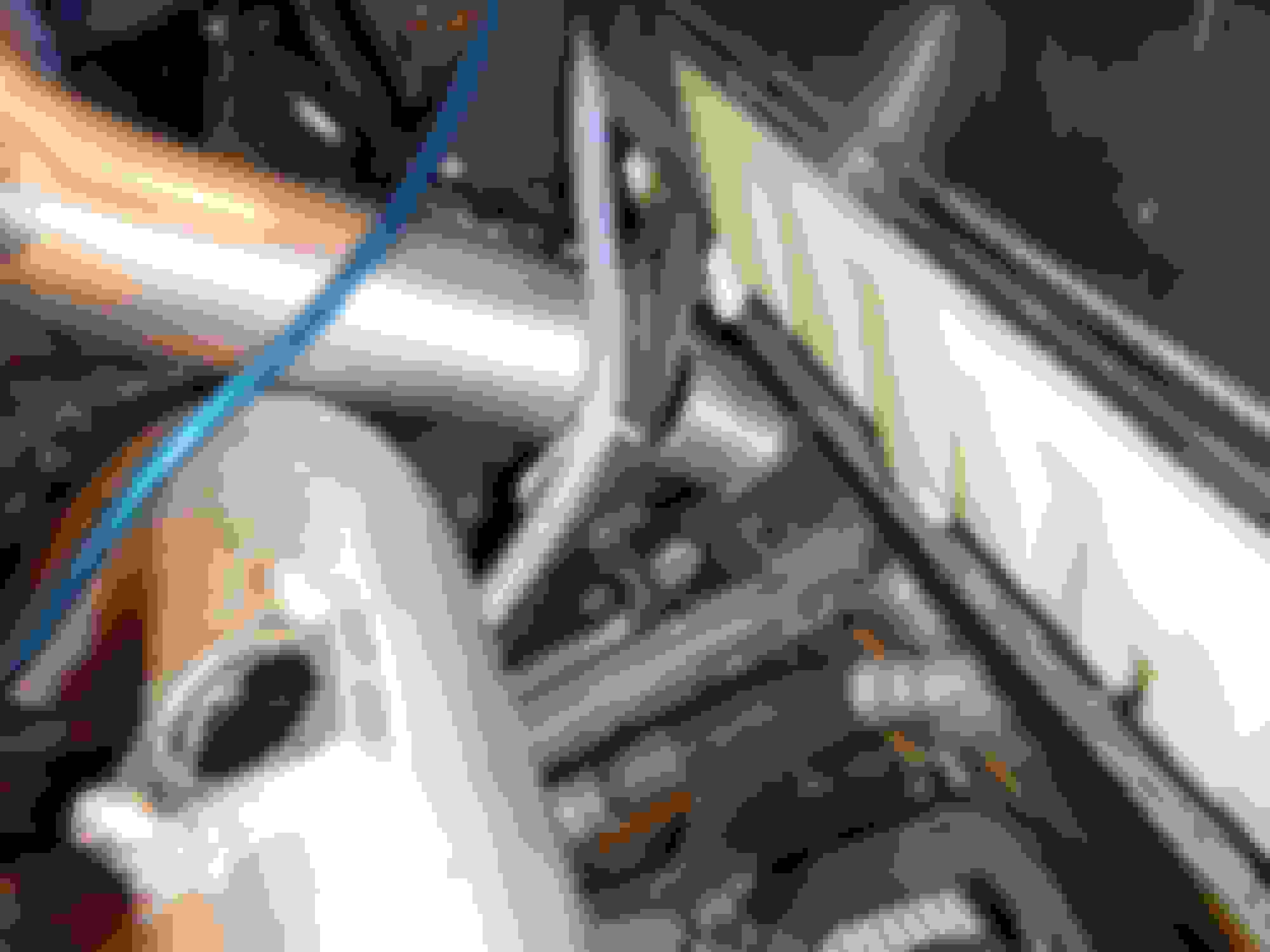
As this is a production kit, it�s a little different than some of the other RX8P kits I�ve seen on this forum. Namely the turbo outlet pipe to the intercooler runs on the outside of the engine bay and through the wheel well. This might be a problem if you�re running aftermarket wheels and tires. I know with my set up (8.75� X 18 and 34mm offset, 245/40/18) I can�t turn my wheel 100% to the right. I can turn the wheel about 450 degrees CW as opposed to the full 540-ish degrees stock. Once again, I�m not sure if this applies to OEM wheel and tire set up. Anyway, sliding the turbo to intercooler pipe in was pretty easy: slide it in from the front of the car, through the suspension members, then rotate until it lines up.
Recirc pipe, is a little more challenging: the engine still has to be jacked up slightly, the turbo feed end has to be inserted first, be careful not to pull out the radiator hose or crack the plastic rad inlet, then the pipe has to be slightly forced and rotated (you�ll know what I mean) through the bay until it pops out by the turbo. I slid the coupler onto the pipe before feeding it through as there�s not enough room to do that once its lined up next to the turbo. The intercooler return pipe goes under the oil cooler lines and chassis member but above the sway bar. The rest of the pipes are self-explanatory
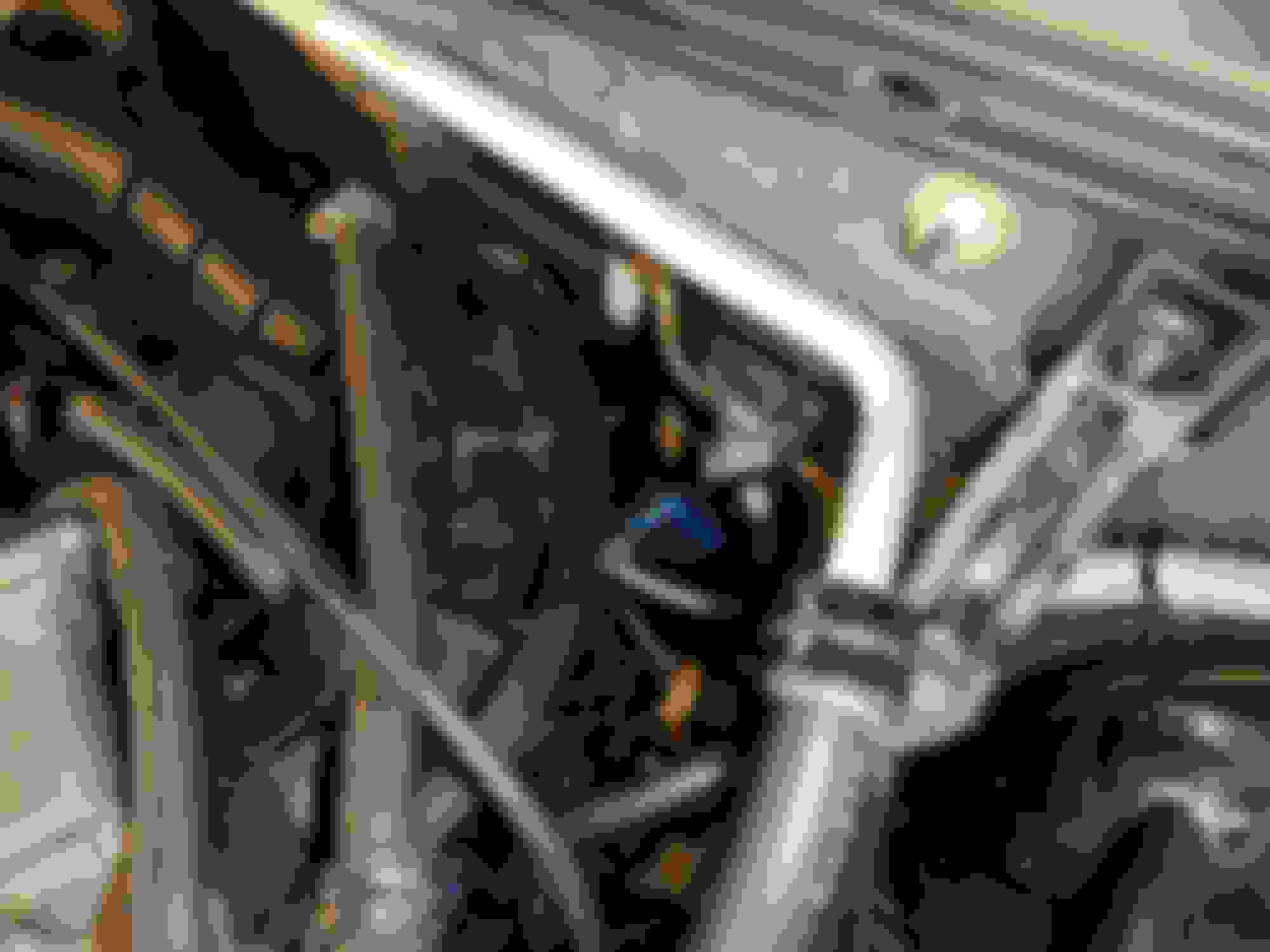
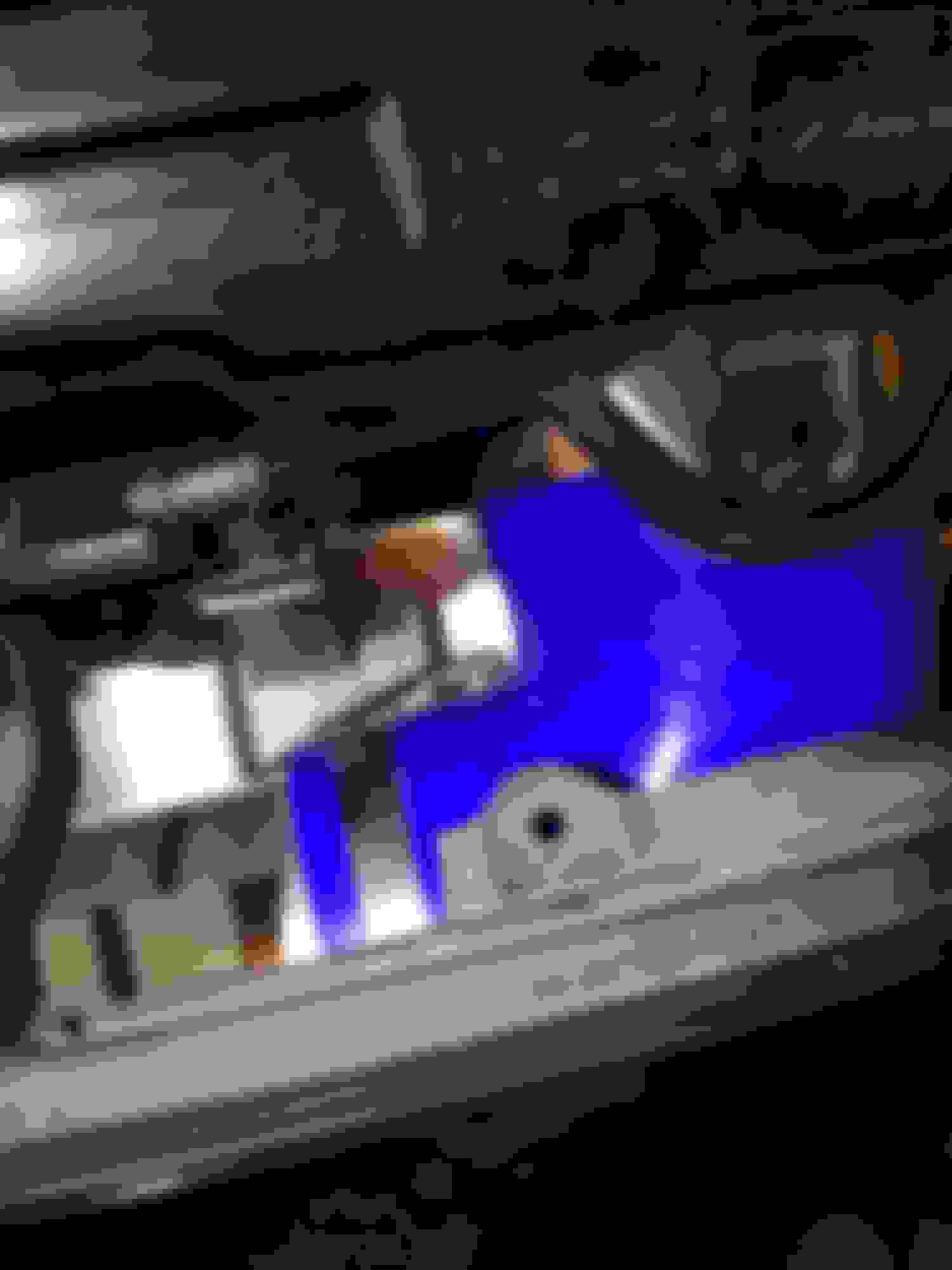
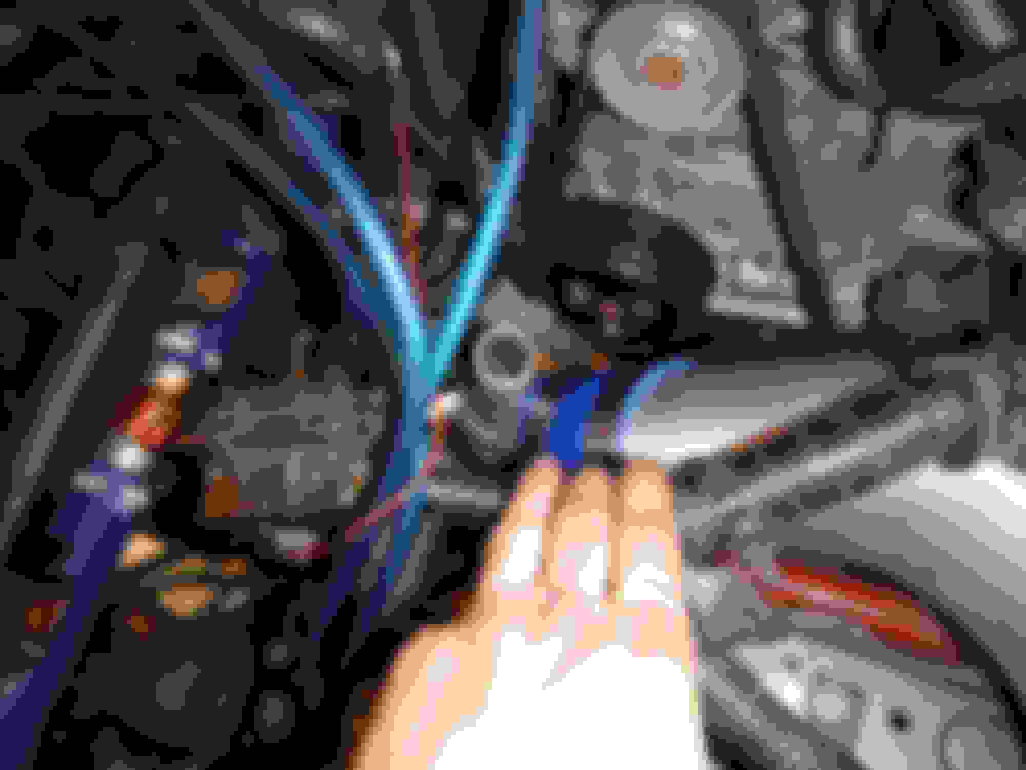
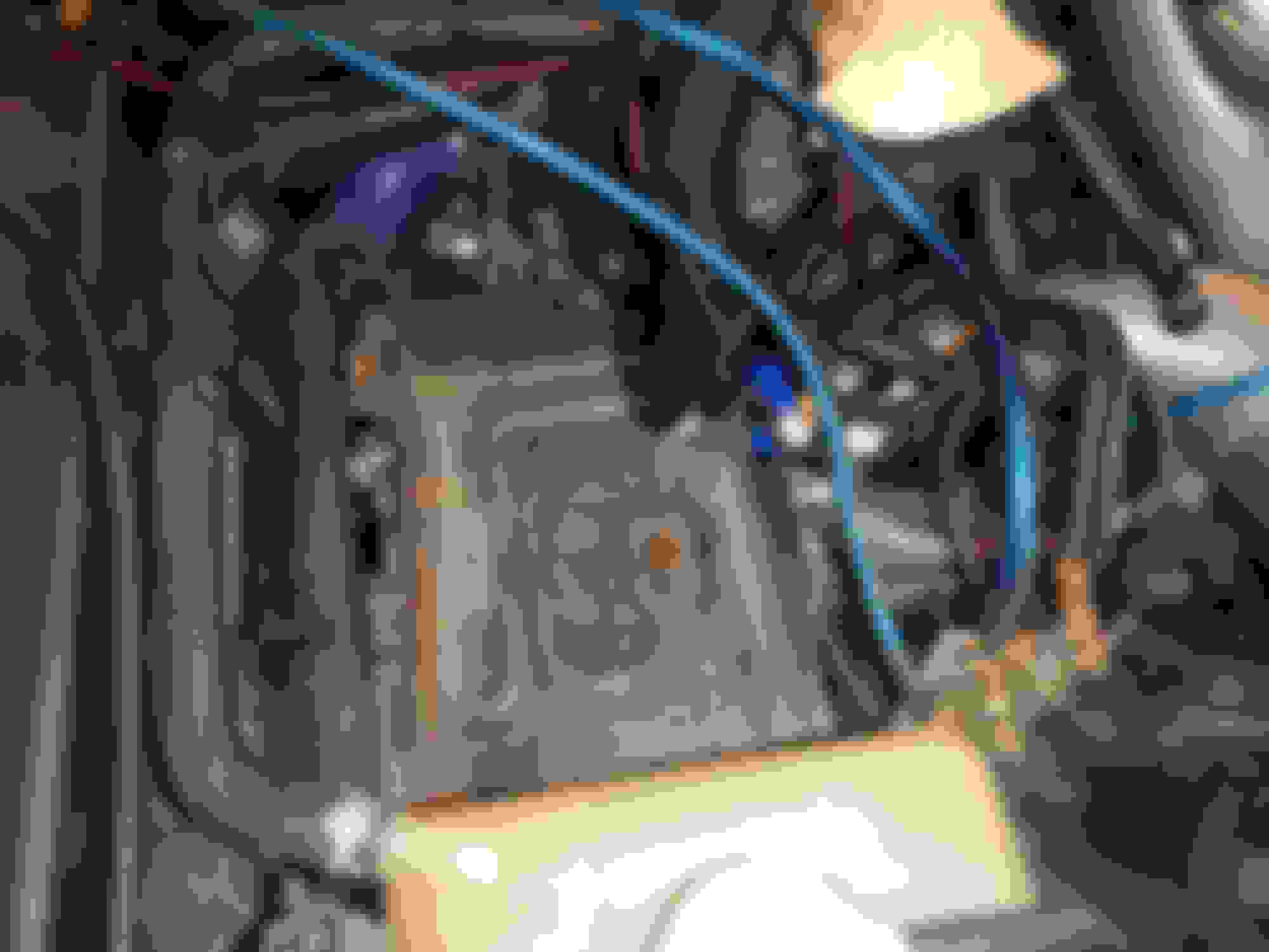
At this point you may also want to consider installing vacuum line bungs into the maf tube. This can be done aftermarket like I did by drilling into the tube and then installing rubber grommets with tubes, OR by asking Scott during the ordering phase. He takes good notes, I promise. You can see those VAC lines in that last picture there kinda half under the grounding wires.
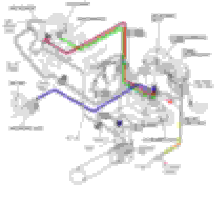
Speaking of vacuum lines, this is a good opportunity to take about routing of said vacuum lines for this particular set up. Here is the final routing of my set up. My car is a 2007 so it has the updated vacuum line routing. What I did was put a check valve in the line going from the Oil fill neck to the LIM. I need this line because they won’t pass me for emissions. Otherwise, you can put a filter on the neck, and cap off the vac line going to the catch can. DO NOT use a filter on the neck, and still have the catch can. That turns into one mighty big vacuum leak. I also put a check valve on the JET air line. Once in boost this becomes pressurized and you leak boost back into your intake. Also bad. The OMP line needs metered vacuum air, so no check valve and it goes back into its original place on the intake (before the turbo). Also, you’re going to need to put a zip tie (or two) or a clamp on the jet air line on the LIM to keep it from blowing off under boost.
Getting the front bumper back on was a bit of challenge. The new intercooler and charge pipes stuck into places so the bumper needed to be trimmed away. I used my dremel tool with a cutoff wheel and the fiberglass cuts right away. I don’t know if you stock bumper guys need to do this but I did because of the FEED type bumper.
Because cooling is a huge concern, I utilized all the holes in the bumper that I could. I took the small bottom openings in the bumper and shoved cooling ducts into them. These ducts directed cool, fresh air, around the intercooler, and directly to the radiator/ac condenser. The bigger openings obviously are dedicated to oil cooling and appropriate ducts have been made.
Now it was time to reinstall the front chassis brace underneath the car. As is, the waste gate and manifold stick out way too far for this to go back on. So, I cut away material from the chassis brace. The result looked like the brace would be completely useless. So I tig welded a bracket of angle iron across the entire brace and gave the whole thing a few coats of black plastidip so it wouldn’t rust.
Finishing everything up, I put my A-pillar back together and reinstalled the battery tray. The gauge pod is a universal on for acura’s that I liberally reshaped with a heat gun.
The gauges are still kind of in the way in terms of field of view and I’ll scoot those over with the heat gun.
The tray needed some minor trimming to clear the recirculation pipe but nothing crazy.
I also installed an oil air catch can and just kind of hung it off the battery box with a flat of aluminum bar I hand bent and drilled holes into. The can was one of those el cheapo empty ebay cans so I slapped some SS scrubbing mesh and copper piping into it the appropriate holes drilled.
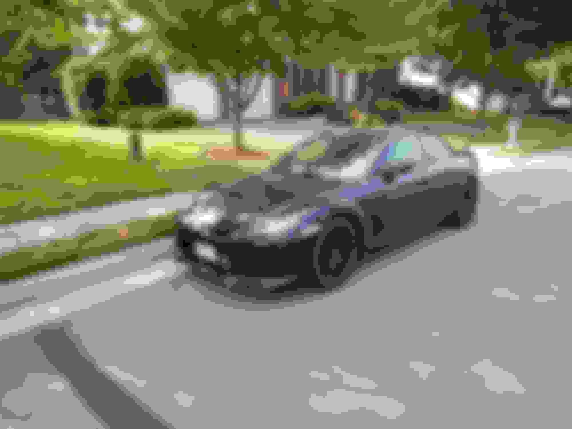
It’s finally done and I took a few glamor shots out on the driveway.
Good luck. I hope it all works out. I would worry about that drain line though the way you have it.
Thanks! So far its been a blast. And I was worried about that too just hanging out there so I put the chassis cross member back over it to give it some shielding and keep it from hanging around.
Great write up . Good to get a full account of what is required to fit this kit .
Where are you at with tuning it ?
Yeah, it was definitely a lot more work than initially anticipated.
And other than were we left off, I pretty much left it as is. Been playing around with A/F at cruise because it was running a bit rich but other than that all the WOT stuff has been bang on.
Yeah, it was definitely a lot more work than initially anticipated.
And other than were we left off, I pretty much left it as is. Been playing around with A/F at cruise because it was running a bit rich but other than that all the WOT stuff has been bang on.
No worries haha. I still have those older toyota injectors I need to send off to get latency tested. Still gotta research and find a place that will make the whole table for me.
 01-15-2016, 02:26 PM