When you click on links to various merchants on this site and make a purchase, this can result in this site earning a commission. Affiliate programs and affiliations include, but are not limited to, the eBay Partner Network.
I installed one last year but honestly didn't notice any real difference as far as readings are concerned. The main reason I replaced the screen is because I've had issues with the screens getting dislodged and sucked in. That WILL cause erroneous readings
This I know, I had this happen and is jacked up my fuel trims and caused me to run stupid rich.
The focus of this discussion is the turbo unit, not the supporting components of the entire turbo system (IC, tune, manifolds, exhaust, etc.).
The two major aspects that limit/contribute to turbo performance are:
Airflow - The ability of the compressor wheel to flow air efficiently to generate boost.
Torque - The ability of the turbine housing and wheel to convert the transient exhaust gas from kinetic energy to the force that drives the turbine shaft
I'll tackle these one at a time starting with Torque. To determine whether the turbine side is running efficiently I've installed an exhaust back pressure (EBP) sensor in the manifold/up-pipe between the engine and the turbo. This will allow me to measure the ratio of pre-turbo exhaust pressure to boost pressure. The ratios taken at different RPMs will determine where my turbine side is operating efficiently and where it is not. Also, it will help me identify maximum boost levels I can safely run at various RPMs while avoiding unsafe high ratios.
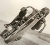
The EBP sensor is basically a tube running from the exhaust manifold to a boost gauge. Critical design points:
Stainless compression fitting and hard line were used to manage the extreme heat and exhaust pressure.
I decided to use a very narrow internal diameter on the SS hard line - approx. 1mm or 1/16". This stops hot exhaust gas flowing up the line towards the sensor, but still allows for accurate pressure readings.
The compression fitting was tapped into the collector before the turbo flange. For external wastegate setups, it would be more appropriate to tap before the wastegate, as we're most interested in the backpressure seen by the engine's exhaust ports, not the turbo.
SS compression fitting is tapped into the collector.
On diesel applications it's common to have several loops of the line to dissipate heat. I decided this was not necessary due to the small internal diameter of the line.
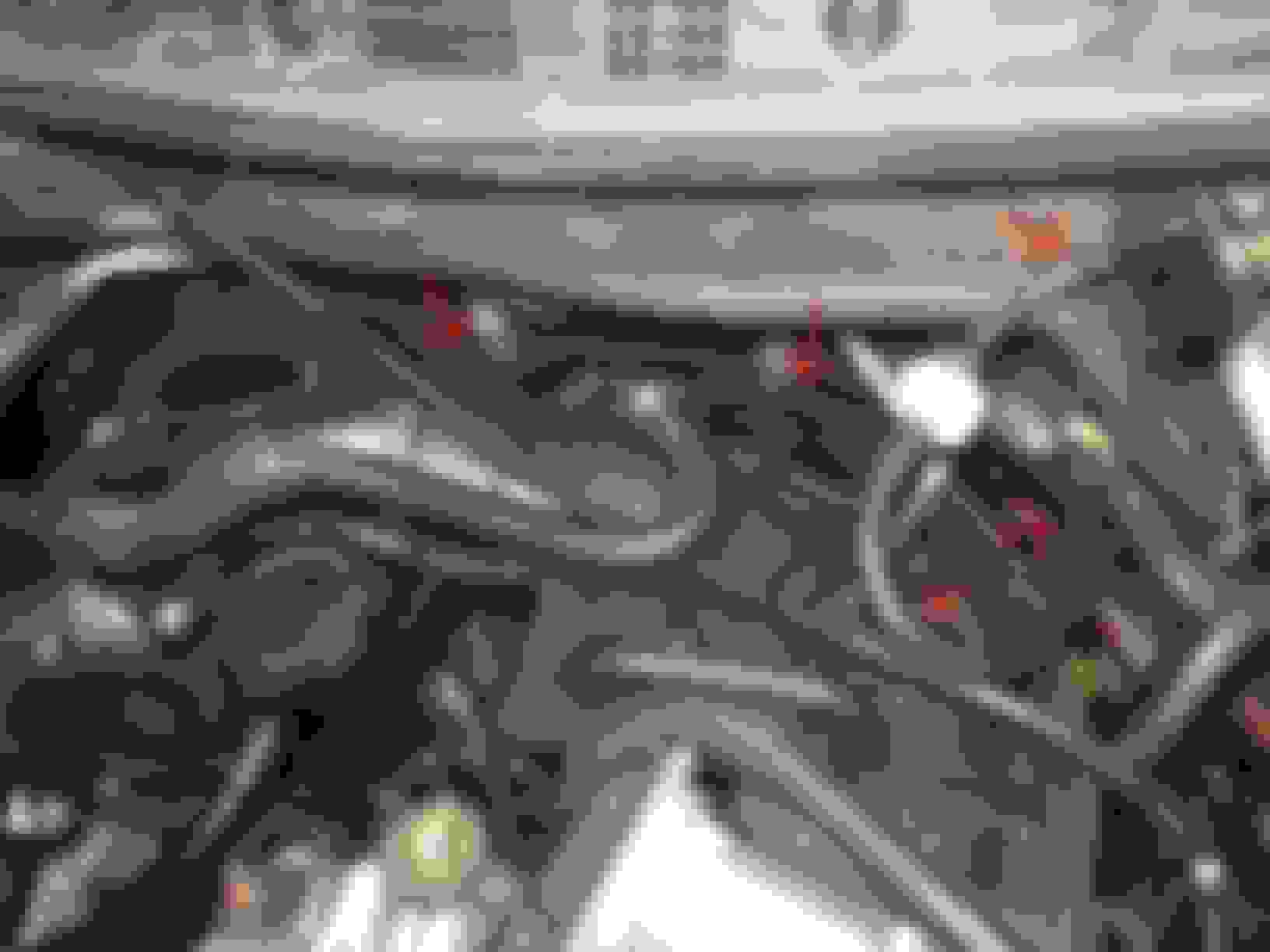
Bottom left is where the SS line feeds from exhaust manifold to transition across the back wall of the engine bay. After a WOT run this section of the line is only warm to the touch, but not hot.
The sensor line feeds into the looped black hose, through a small white filter and into the electric pressure sensor (black box)
Last edited by JimmyBlack; 11-24-2015 at 08:34 PM.
Well that'd just kill any suspense if I posted the results straight up.
I'm actually still gathering data so I can provide a video of the gauge in action and also a graph of RPM vs. boost, pressure and ratio.
One thing I'll tell you straight up though, if you are running a standard Greddy T25 housing and turbine wheel (12 blade unclipped) you should not use an EBC feature (often called Sensitivity) to maintain target boost through the higher RPM range. Instead, let it taper off towards the redline like it wants to. Doing this will avoid excessive back pressure (read HEAT) on the exhaust ports. Excessive back pressure introduces the risk of detonation and exhaust port overheating.
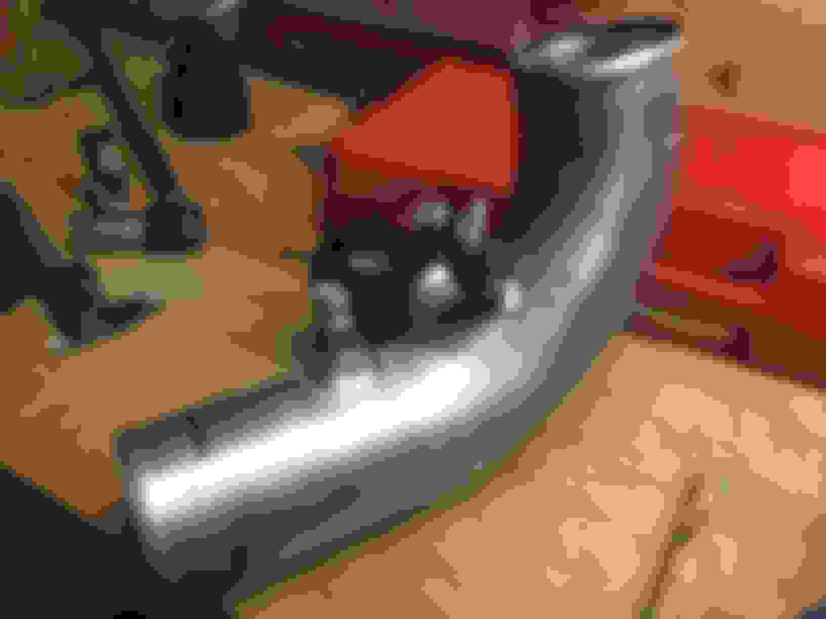
Found some time today to grab some stats for a comparison between exhaust port back-pressure and boost pressure. It's been a bit of a callenge presenting the graphs clearly so if anyone has any suggestions for better formats let me know. Can provide raw stats if anyone is interested.
Test 1
Same boost profile, different gears.
I completed runs in 2nd, 3rd and 4th gears. Results were consistent, but didn't show a huge variation. Lower gears showed slightly lower boost levels and slightly higher Exhaust:Boost ratios than the higher gears. No surprises here, as the lower gears require the turbine wheel to accelerate up to the suitable flow speed much faster than the higher gears.
Test 2
3rd gear, different boost profiles.
I used the EBC to complete two runs, the first run with settings zero'd to get as close as possible to the natural WG actuator spring setting. The second run spooling as quickly as possible to 11psi and maintaining that as long as possible as RPMs increase.
The assumption here was that the run with the higher boost would result in a higher Exhaust:Boost ratio. This was based on my working theory that the T25 housing is restricting exhaust flow, then releasing a majority of the exhaust through the internal WG port leaving only a small portion to spin the turbine wheel.
The results show that exhaust pressure is not just about the exhaust flow rate. My own conclusion is that Exhaust:Boost ratio is affected by the compressor wheel. In the case of my turbo setup, it appears that my compressor wheel is deeper into the efficiency island with higher boost levels, with an end result of less force required to spin the turbine wheel, resulting in less exhaust back-pressure.
In terms of how this will change the way I run my current setup, my initial plan is to work within the following guidelines. This may change depending on forum feedback on this post.
Run with maximum back pressure below 25 psi. This is an arbitrary value that I've chosen. Managing excessive exhaust back pressure should to avoid over-heating the engine exhaust ports and siamese sleeve insert. It should be possible to manage this by reducing redline RPM, adjusting EBC, and possibly reducing the spring pressure on the WG actuator so it releases sooner at high back pressure.
Run with a maximum Exhaust:Boost ratio below 3. Ideally closer to 2.5 (Corky Bell's recommended maximum).
Run boost levels up to 16 psi in the low to mid range while meeting the above goals. Running boost this high should provide better Exhaust:Boost ratios, but is only possible if other parts of my turbo setup are up to scratch (E.g. tune, air temp, fuelling).
It's getting late, so I'll write up more about why Exhaust:Boost ratios are a useful later.
Firstly .... Excellent work man . This is the first time I've ever seen anyone do this on a Renesis and could be another step forward in our attempts to make power from this engine .
Why didn't you run to the redline ?
As far as how you run your setup goes .... my feeling is that for short bursts you are ok to run such high ratios so long as you are not getting any detonation . Where I can see the issue killing an engine is under sustained high boost ... IE track
Your efforts have motivated me to see how my setup compares . Have already got the holes drilled and fittings are underway.
Thanks. Interesting what you say about guidelines to run the turbo at. Reading between the lines, I now have the Brettspeed endorsement to run higher boost on the street
Originally Posted by Brettus
Why didn't you run to the redline ?
I was concerned about running such high exhaust pressure, and more importantly my boost gauge for exhaust pressure only goes up to 30psi.
Originally Posted by Brettus
Your efforts have motivated me to see how my setup compares . Have already got the holes drilled and fittings are underway.
Happy to hear this. With your different sized turbo, our combined results should give a pretty good view of this topic.
I suspect that your setup will display much healthier back pressures and EB ratios, which means in theory, you should be able to run your turbo hard (more boost, more RPMs) at the track with much less risk of engine failure.
Originally Posted by Brettus
Where I can see the issue killing an engine is under sustained high boost ... IE track
It's likely that your Greddy 60-1 turbo setup saw much less exhaust pressure at high RPM than my setup due to the clipped turbine wheel and more efficient high flow 60-1 comp wheel. I'll have a chat with you about this before I run more boost at more RPM as I'm not convinced it's safe to run
My goal with this sensor was to get a better measure of how efficiently the turbine side is performing so I can better understand the most appropriate upgrade path. While I could possibly have upgraded to a GT3582 like Brettus, I wanted to school myself up and see if I could understand how each component contributes to the overall performance. Work in progress lol.
Something I haven't clearly explained yet is why I'm looking at EB (Exhaust:Boost) ratios to identify turbo efficiency. I was researching why some turbos produce more power than others that are running the same boost. This point is not clearly documented in many forums or text books. The most common forum answer was that a larger turbo has the capacity to flow more air to replace the air that is swallowed by the engine on the intake cycle. This explanation is not accurate. The efficiency is directly measured by the EB ratio of the turbo. The lower the EB ratio, the more efficiently a turbo works. Consider two turbo setups, both running the same fixed RPM and boost. The first has a high EB ratio (exhaust manifold back pressure), and the second has a low EB ration (exhaust manifold back pressure).
Lower exhaust pressure -> less choked exhaust ports -> improved VE -> more power at same boost.
This is all assuming that the low EB ratio scenario is capable of spinning the turbine shaft effectively. The trick is to find the best combination of compressor wheel, turbine housing size and AR and turbine wheel to achieve lowest EB ratio possible while still maintaining the target boost levels through the range. There are always compromises, but some component modifications will prove to be much more effective than others. This is the area I'm focussing on.
Back in the real world, some race cars have achieved EB ratios of lower than 1. This takes a huge amount of trial and error to get the most efficient combination of turbo components. For street use, it’s more reasonable to aim for an EB ratio between 1 and 2 across the RPM range. If you can achieve this, you’re using a suitably sized turbo for your setup, and that for the same amount of boost, your car will be generating more power than the next guy that has the same boost but a higher EB ratio.
My turbo pushes 330g/sec max flow on the higher boost setting in the graph above. This is nowhere near what a larger turbo would flow at the same PSI. As stated in a previous post, this efficiency is made up of the compressor wheel efficiency at this flow rate and boost pressure, and the ability of the turbine housing to utilise exhaust gas to apply torque to the turbine shaft.
I'll ignore the cold side (comp wheel) for the moment, as the benefits of comp wheel swaps and flow maps are already reasonably well documented. Instead, I’ll focus on the hot side (turbine) modifications that can be done to lower the EB ratio and improve efficiency, as this is the area I know least about.
Looking at my small fast spooling turbo, I'm looking at the following options for modification.
External wastegate
11 blade turbine wheel (apparently this is more efficient than clipping)
T3 turbine housing (requires custom exhaust manifold)
Different turbine housing AR (only available with T3 housing)
With the suitable selection(s) from the above, I should get significant improvements in peak power while retaining most of my low end spool.
As I stated in my previous post, increasing my boost level reduced my EB ratio. My conclusion is that the compressor wheel is more comfortable flowing air at this higher rate and pressure. So in addition to the turbine modifications above, the EB ratio can be improved with a suitably sized compressor wheel. Pretty obvious, but nice to see this in the results.
I realise that my conclusions and list of mods above are not ground breaking, but it is nice to have measured results to back up all the hearsay and pseudo-science around turbo sizing.
Next Steps
1. Dial in the tune (more beer for Brettus)
2. Up the boost and take some more measurements to see if I can get any more useful info with my current setup.
3. Chat with my fabricator about installing an external WG flange on my Greddy manifold.
I now believe that the T25 may be capable of flowing a lot more air than I originally thought, based on Brett's 360whp results with his 60-1 comp wheel and clipped turbine wheel. This is why I'm looking at feasibility of running an external WG on the Greddy manifold as the next turbo modification.
I particularly like the idea of measuring this parameter as it's the only EASILY measurable thing that can tell you if the changes you made to your system made any difference.
EG any change to pipework diameters, turbo , improved bends, Exhaust diameter, intercooler etc etc .... will show up as an improvement in pre turbo exhaust backpressure . If they don't show up .... you can be sure you are looking in the wrong place for gains.
IAT sensor relocation complete. Now located in C6 (pre-TB) charge pipe for more accurate intake temp readings.
I had a threaded bung welded into the C6 pipe as I didn't trust the pipe wall thickness to hold the sensor securely. Sensor calibration took a bit of time. GM sensor datasheet values were way off, and the values from Harlan's useful post here were also inaccurate for my car. I ended up comparing OBD2 readings from the new sensor against a hand held digital thermometer at different air temperatures between 25-60C ...using my wife's hair drier.
I observed that the GM "fast response" sensor updates about every second, and can change at a rate of about 2 degrees C per second.
With the sensor located post-turbo and post-IC, there is a much better view of how intake temps vary in different driving conditions. I was hoping to see temp spikes during extended WOT high RPM pulls to give me an indication of whether my compressor wheel is suitably sized. This may be visible to a sensor placed pre-IC, but is not visible from my sensor's post-IC location.
Observed temp increases and decreases are both very gradual. It takes some time stopped at the lights before temp starts to rise, and takes a similar amount of time once cruising again for temp to drop back to previous value again. These are actual temps, as I know the sensor responds much faster than the observed temp changes.
This indicates that heat soak of the charge pipes is the largest contributor to intake temp changes. I've ruled out the IC from being a contributor to raised temps as I would expect temps to drop quickly once cruise speed is reached, however this is not the case - temps remain high until fresh air is flushed through the intake piping - typically 30 seconds or more at cruise, or a short WOT blast up to cruise will do this.
Based on the above, there are benefits in insulating charge pipes so they don't get heated by elevated engine bay air temps. Using exhaust wrap I've insulated the C6 pipe, as this pipe is most exposed to high engine bay temps. This has reduced my intake temps by several degrees compared with before the change, reduced the temp spikes while sitting at the lights by about half, and return temps to normal slightly faster once cruising again. E.g. where ambient temp is 20C (68F), I'm now seeing something like 25C (78F) instead of 30C(86F) after sitting at lights for 2 minutes.
If anyone is looking to do this, exhaust wrap will be more effective than reflective DEI tape as the heat coming at the intake pipe from the engine bay is conductive rather than radiant.
New IAT sensor location:
Wrapped C6 intake pipe:
Yes, it was a bitch to wrap.
Last edited by JimmyBlack; 12-06-2015 at 05:16 PM.
Would you mind sharing that scale. I've experienced the same thing and slowly been adjusting it.
I think running the turbo out of efficiency range won't hurt too much if you can pull the Temps back down before they go into the engine. I ran for quite a while with a uncooled intercooler and would see iat of 130f on a 1-3rd pull from 20 to 96mph. It would slowly click up from 100ish. Then take about a minute to fall again from internal airflow.
Now that I have the water in the system and the pump on i see it creaping up from 100 to 107 or so and it takes 20 seconds to fall back.
If you were in a bad efficiency area to see losses you should also have a significant heat increase. If your raising pressure and your Temps aren't raising you are sill getting more airflow. That is why flow is key.
pretty much what I see on my setup James . Have not insulated that pipe but one area I did insulate was where the intake passes over top of the radiator .....
I have some IAT logs from separate track days somewhere ....one on the greddy and the other on the GT35
pretty much what I see on my setup James . Have not insulated that pipe but one area I did insulate was where the intake passes over top of the radiator .....
I initially discounted wrapping the suction pipes because of their pre-IC location, however during stop/start traffic, the suction pipes would get heat soaked, esp. from hot air from radiator fans, and the IC would do little to assist cooling while stationary. With this in mind, wrapping all suction pipes between air filter and turbo compressor inlet would further reduce temp spikes while stationary. Wrapping the C6 pipe only has got my temp spikes well under control, so not worth me buying extra wrap to do this now.
Having said that, if I did have any exhaust wrap left over I would definitely be happy to spend the time to wrap first the S1 suction pipe in front of the pulleys, then the MAF pipe to further reduce heat soak of the intake pipes.
Last edited by JimmyBlack; 12-06-2015 at 11:43 PM.
I'm seeing 20 psi turbine pressure at redline and 10psi boost pressure.
I knew you wouldn't make it to your 1000km engine run in lol
Lemme guess, after we talked you went to the garage and checked the oil, found it was clean and thought, "Yup, time for some more boost"
Summarising the info you've posted on this, you're coming on boost to about 16psi, then tapering to 10psi at redline, with EB ratio of 1, climbing to 2 at redline. Those ratio figures are great, and that ratio is only going to get better as you crank up the boost pressure at high RPMs, when the boost PR goes deeper into the efficiency island of your turbo comp map.
You'll have to figure out what maximum exhaust pressure you are comfortable running, as this will obviously increase with more boost also. Like you've said before, it's probably not a big deal running high exhaust pressure (e.g. 35psi) for short periods, but shouldn't be done for extended periods, e.g. at the track.
I now have decided on my turbo upgrade path (thanks for your input here Brett).
For now I've ruled out a custom manifold to T3 turbo, as I now understand that the T25 housing is capable of flowing a lot more exhaust gas than I initially thought....sooooo, the low mount EFR with cut away trans. tunnel will have to wait for another 12 months Instead, I'm planning to upgrade my current turbo to a "Baby EFR" by way of a very nice light weight turbine wheel, retaining the T25 housing.
Current Turbo
Comp wheel: Custom - Billet 76mm wheel with 56 trim in a ported comp housing.
Turbine wheel: Stock Greddy - TD06H 12 blade in T25 turbine housing with internal WG
The 60-1 will spool slower than my existing wheel due to the increase from 55 trim to 60 trim, so forged (billet) is the only sensible option here.
The 9 blade turbine wheel is a light weight model. Apparently it spools better than the stock 12 blade unit, as well as flowing a lot more exhaust gas for improved top end, making this a very nice upgrade. This turbine wheel will allow me to run the 60-1 wheel without too much impact on spool and with significantly improved top end. All up this should be an excellent upgrade with major benefits and minimal drawbacks.
To compare my proposed setup to a known turbo, the Garrett GTX3576R turbo uses a similar ported housing to mine, but the Garrett has a 58 trim compared with my proposed 60 trim wheel. Therefore my proposed compressor side comp map would flow slightly more than the GTX3576R, closer to the GT3582R in the map below (note that turbine side is ignored when looking at compressor maps).
All estimates, no guarantees...but I'm pretty excited about the next step forward. Will probably be installed around February 2016.

 11-18-2015, 06:36 AM


 I had this happen and is jacked up my fuel trims and caused me to run stupid rich.