When you click on links to various merchants on this site and make a purchase, this can result in this site earning a commission. Affiliate programs and affiliations include, but are not limited to, the eBay Partner Network.
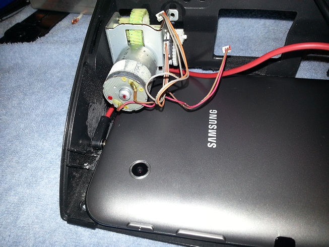
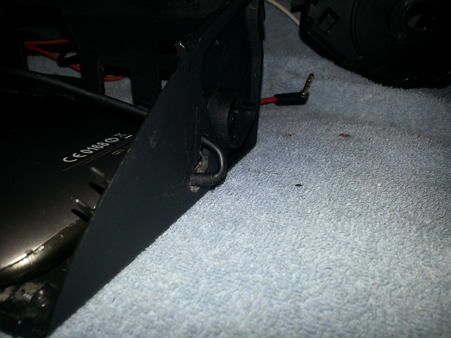
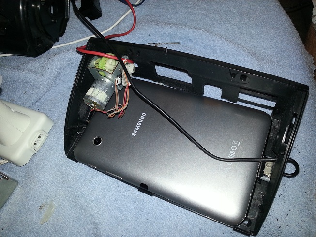
Hey everyone, just finished installing a Galaxy Tablet 2 into my Rx-8, Special Thanks to all the people and info I found here.
Not going to do a "How to", but feel free to ask questions.
Shots are not in order.
My question is which wires do you connect to where for the motor to flip open and tilt? Considering your vehicle did not come stock with the oem navigation and mine does not either.
I have gone down this route and purchased a sat nav enclosure and when fitting I made a bit of a bo bo with the cabling and (cut a long story short) have damaged one of the PCB boards. At the moment I am opening the enclosure by hand which is not the end of the world but would be nice to use the buttons.
My question is
1) Does anyone know where I can get a cheap replacement?
2) Is there a custom board that can be purchased instead?
3) Can this board be repaired (cheaply)?
As long as that IC is the only thing damaged, its easy to repair (if you're comfortable with soldering).
But you'll need to find a replacement component and the JEDEC (or the writing on top) is probably not readable anymore.
If you're able to get a replacement IC, simply remove the damaged IC, clean the area with IPA and a brush, then solder the new IC on.
If the board masking got damaged, they make masking pens to cover it and hopefully the traces are OK.
I work for a company that builds and reworks PCBs so this may not be too terrible, just finding the correct IC might be a challenge unless you can reference an undamaged board to get the info written on top.
Good luck!
I am definitely not comfortable with soldering and the IC has disintegrated. Sounds like I will have to be on the lookout for a cheap replacement but I very much doubt they come up as everyone want the PCB with the enclosure.
I read the first 3 pages and didn't find the info I need, so here goes.
I have a nook color that has been rooted to Android laying around, has anyone tried fitting one to the OEM Nav hood? Also, I don't really care about the ability for the Nav hood to go up and down, is there a way to just keep it locked in the up position for a simpler install (No arduino, etc)?
I really only want the ability to play music, use Tourque, and have Navigation (which I will tether from my phone, or DL maps from google maps).
As long as you leave the motor and gears in the hood it will stay up on it's own. You can still open and close it by hand.
Originally Posted by aorkennykiller
I am interested in using a galaxy tab 4 for a car PC. Has anyone done this before?
Also it seems as though the white tab has an extra .5gb of ram in it. Does the color of the bezel show when installed into the navigation housing?
As long as the very outer dimensions are the same as a Galaxy tab3, it should work fine. Same for the screen, if it's the same size you will not see the tablet itself, only the glass.
So I just hit 4 years to the date with the tablet in my car... Sad to report the screen has begin to show early signs of failing... It has started to show "burn" marks in the screen. Considering the car sits outside, in the sun 24/7 in Louisiana heat, this was going to happen sooner or later. I will soon begin looking for a replacement tablet. Still very proud it made it this long and I never once had to remove it to repair it.
I buyed a used and modified gps unit with samsung tab 2. It has the usual (acc, b+, gnd, ill.) wires and connection, but the "system" don't want to work.
After many hours to read all thema in these topics, the wires soldering looking good.
The unit is delivered with this realization (with not to nice solution and soldering):
[IMG]https://www.rx8club.com/attachments/series-i-interior-audio-electronics-24/177984d1318935544-car-pc-hood-controls-w-o-custom-pcb-issue-lcdpinout1.jpg[IMG]
+ the "extra" 1O wire.
The motor is working, i checked it. Illumination is to.
The buttons don't controls the motor/hood in either direction - und there is no sign or noise for that from the motor.
But the outer pcb has a little problem...
The seller don't say anything about this fault, he sell as worked fine.
So when it is fine, what can be the problem?
Any opinion!
Best regards
Sorry for my english!
Atti
Looks like there was a short in the circuit board....that one trace has definitely been hot. The soldering is poor....you might want to confirm that it has been wired correctly before you assume that something has been blown from the short.
Otherwise it is likely that your board is toast
That looks like a ground trace on the board, if it gets hot enough it will lift, usually do to a short or a component failure. Whoever soldered needs some lessons. Like Dannobre stated above, make sure it is correctly wired, then resolder all of them to get rid of the cold solder joints(dull gray joints are cold solder and will eventually fail), use flux (no clean flux or make sure to clean really good after) then use heat shrink on the wires to prevent shorts. Buy some solder mask and apply to the trace to prevent shorts.
Thanks for the answers, i hope we can something to figure out with this pcb.
The wired are correctly, the solderings seems sufficiently tied to, but i will check it again with some expert. After the end of the failured can measure 12v, so it is not breaked, and on the other pcb can + and - measure to. So i'm a little hopeful, that this shopping was not useless..
Check for shorts, I can see an exposed trace above R791 and solder splash to the left of it where the wire is soldered, that is a big no-no. Also, being a multi layer board, you may have traces with hairline cracks that will lose connection after you apply power, heat makes the hairline crack to separate. One last thing, check the fuses for conductivity, they are there to protect the board. Usually resistors with 000 on them are "fuses", any other number is the resistance on them, looks like R780 and R913 are fuses (R=resistors, L=inductors, C=capacitors, etc)
Oh I would really love to do this to my car but I'm afraid I won;t do it right,,is there anyone that lives in Fort Myers,Fl. that could do this for me??
I have my Nexus 7 tablet hooked up where my stereo is. For the life of me, mine keeps dying even though I have Tasker kill the tablet (turn off) after 5 minutes without battery! Anyone have any idea / solution as to where they hook up the tablet and everything? I tapped into the wires for power for the cigarette lighter.


 10-01-2015, 01:53 PM


 ):
):