DIY: Blank CD Iphone Aux external controls
 09-16-2011, 09:32 AM
#1

DIY: Blank CD Iphone Aux external controls
Moving this old post to another forum so the pics can be displayed as more than links. I'm deleting the old thread as well.
Let me start with I cannot be held responsible for any damage caused to you, or your property.
Now that that's out of the way I'll actually start with what this set-up is and what it will do. The purpose for this setup is to utilize the silent CD method of listening to an aux source, and incorporate the user controls the iPhone's mic/headphone combo provides. So basically when I plug my iPhone into my aux cable instead of only having control of the volume via steering wheel, I will also have control of the song(skipping tracks, pause and play, and answering phone calls) via an external switch akin to the microphone squeeze switch on the iPhone's combo headphones.
Things you will need for this project:
� 1 Quad-contact pushbutton switch (you can get these from radioschack or just break some electronic device you have with a clicky button)
� 10ft. approximately of stranded ~20 gauge wire
� 1 Small microphone (I used the Mic out of the iPhone headphones)
� 1 Four conductor audio jack/cable with 3 sets of wires attached (these are common with A/V cables that come with televisions and dvd players.
� 1 Three conductor audio jack/cable (optional)
� Heat shrink tubing or electrical tape
� Small section of circuit board (optional, but it�s helpful)
� Soldering Iron
� Solder
� Phillips head screwdriver
� Hot glue or epoxy(optional)
� 1 Multimeter
Circuit:
paper-circuit.jpg?t=1240440114
This picture shows that one 4-conductor jack with contacts from tip inward (left, right, ground, microphone) is reduced to a 3-conductor jack (left, right, ground) by splitting the wire corresponding to the innermost contact and ground. This split set of wires will connect to the switch and microphone. The other two sets of wires correspond to the left and right channel audio signals. Those continue to A.) Another jack B.) The stereo C.) A set of L/R wires already soldered to the stereo.
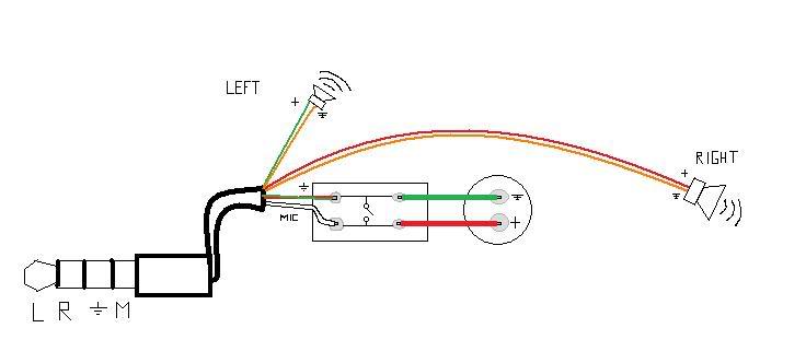
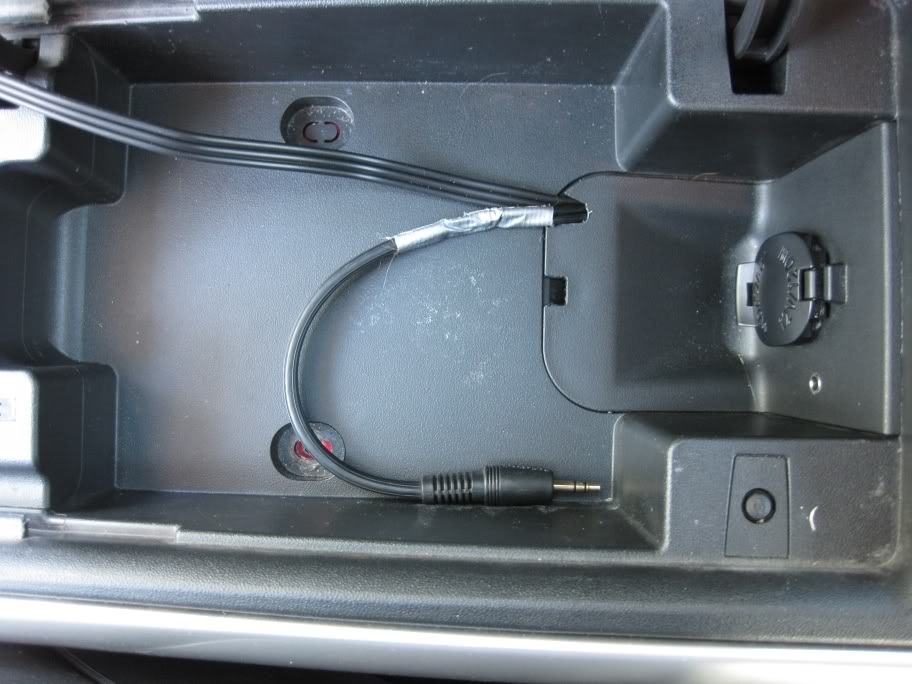
This picture shows how the iPhone�s headphones are wired. In my case the left and right sets of wires proceed to connect to another 3-conductor jack, as in the first picture. In my car I have a L/R audio cable soldered directly to the stereo which runs through the center console and connects to a female 3-conductor audio jack. This is why my L/R wires will re-terminate into a 3-conductor jack and in later pictures you will see the jack next to the 12V socket.
Wiring
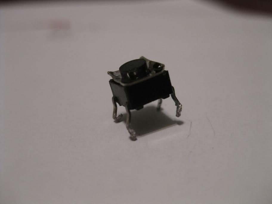
First we start with our pushbutton switch. This is represented by the rectangular shape in the previous drawing. The way this switch works is simple. When the button is depressed the 2 signals are shorted together. Using a multimeter you can determine which two legs will be connected when the button is depressed and which two will be connected when the button is not depressed. You will want to solder the microphone�s ground (on the mic) and the microphone ground from the 4conductor jack to two of the legs that connect through the switch when the button is not being pressed. The same principle applies to the positive mic lead and the mic signal from the jack. Now when the button is depressed the microphone signal and the microphone ground will short together. This tells the iPhone that it needs to start/stop/answer a call (one press). * If you use the microphone that came from the iPhone headphones the positive lead is red and the ground lead is green (on the microphone). *
The wiring is a little weird. Your 4conductor jack will be the end you see normally and the rest will be hiding. So let�s start with the 4conductor jack side. From the tip of the jack, as mentioned above, you have L, R, Ground, & Mic. On the other side of the jack there should be 3 sets of wires. One for the left signal and a ground, one for the right signal and a ground, and one for the mic signal and a ground. In my case I split the mic/ground from the L/R wires before tunnelling into the console because of the female jack I already had installed. For me this was about 2 feet of cable (I want to be able to pull the iPhone out of the console while it is still attached so passengers can select music or whatever.) The length of your cable and the length before the split from the L/R wires are up to you.
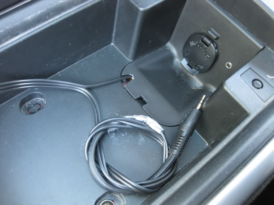
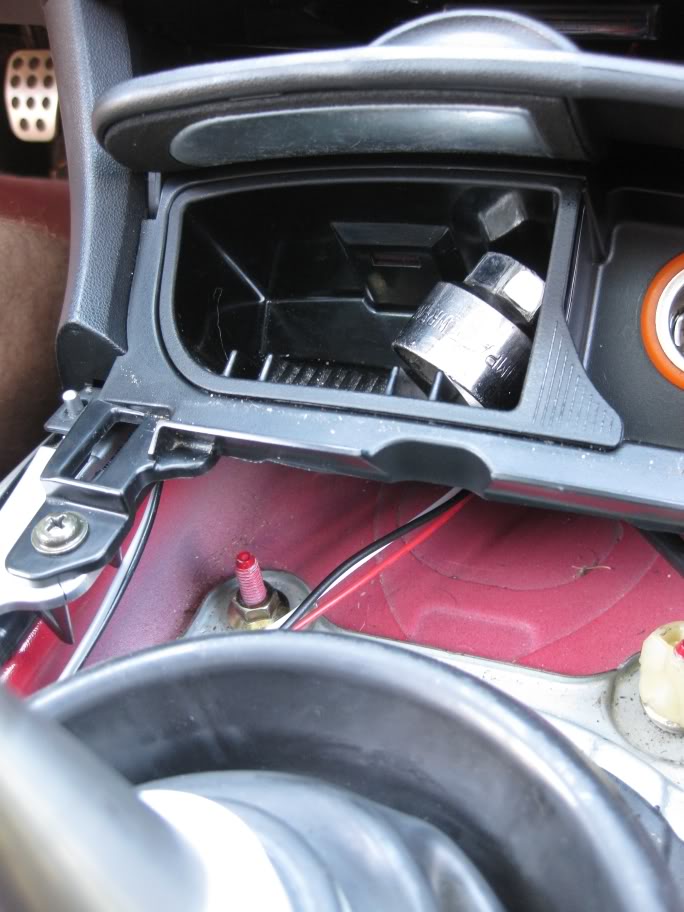
In the picture above you can see where the L/R split off from the Mic cable and terminate into a 3conductor jack. You can also see the female jack I installed before.
Now from that split, the mic/switch wire runs forward under the console to the left of the shifter, behind the plastic where your right knee rests and up behind the steering wheel. **This totally depends on where you decide you want your switch. I thought about having the button near the seat warmer switches, but if I screwed up with the dremel it would be very apparent to anyone sitting in the car.** That being said, I used about 5 feet of stereo wire for that task. The following pictures are how I routed my wires and where I placed my switch and the mic.
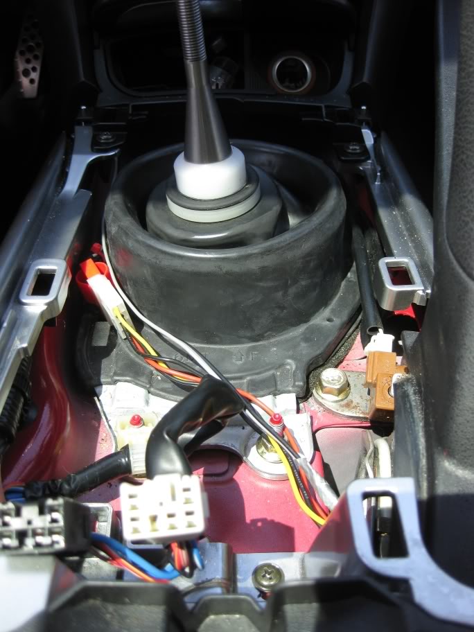
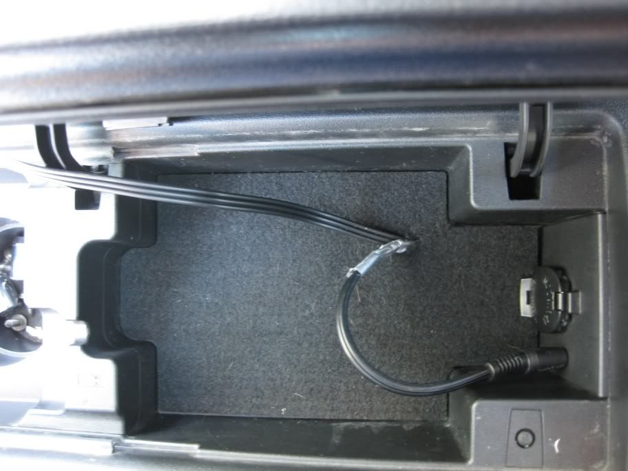
The wires in question are the greay/black stereo wires. The other set of wires goes to the head unit and are the L/R cables. If you choose not to terminate the end of your cable with a 3conductor jack like me then the rainbow cables in my picture would be the L/R audio cables for you.
jump off to the left of the trans. tunnel into the driver's footwell.
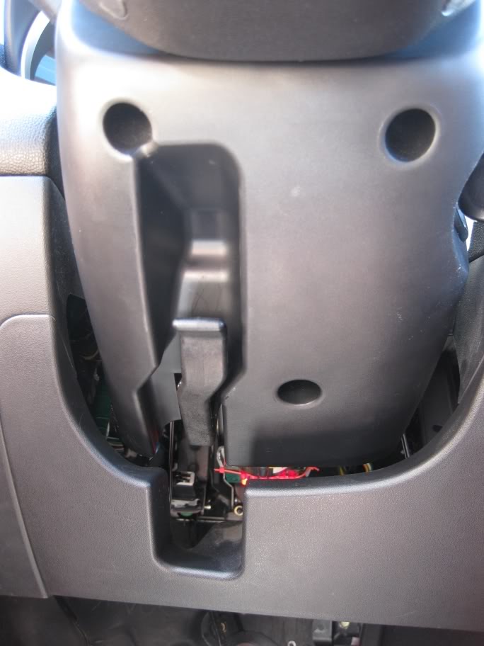
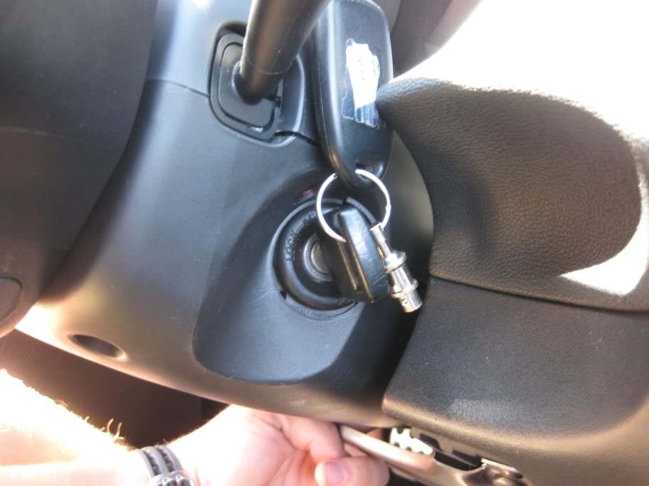
Unscrew the 3 screws holding the cover on for the wheel.
snap the left side down and apart
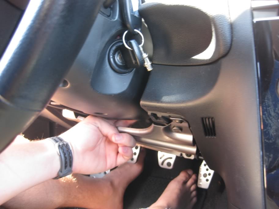
snap the right side down and apart
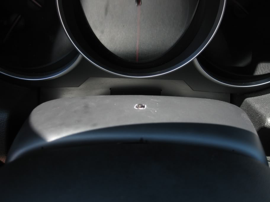
Now the top(where I drilled a hole for my button and filed out into a square) can be removed.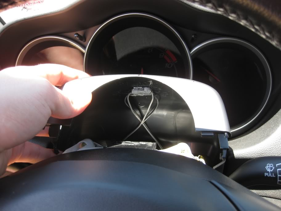
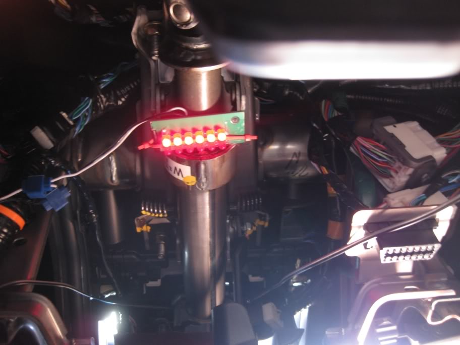
You can see the portion of breadboard that my pushbutton is on. I put hot glue around the sides of the switch and on top of the breadboard. Even though I don't think the switch would slide, it was a perfect fit for height right there.
From this point I used another 5 or so feet of wire to run the mic somewhere where it could easily pick up my voice. (Instead of soldering the mic leads(green and red) directly to my pushbutton I soldered them to 5 feet of stereo cable and then wired that to the pushbutton)
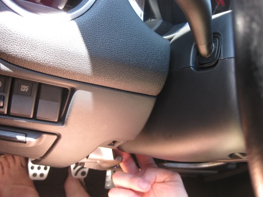
In the following pictures I show the route I took to get the mic to a good height.
You can see the wire running up to the switch (left) and down toward the mic(right)
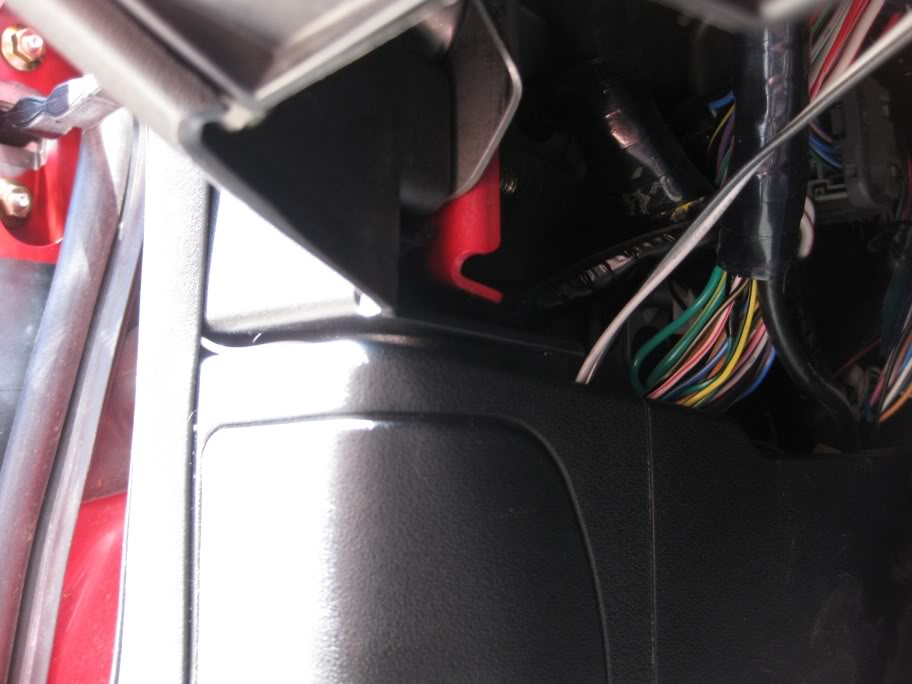
Into the crack above teh fuses
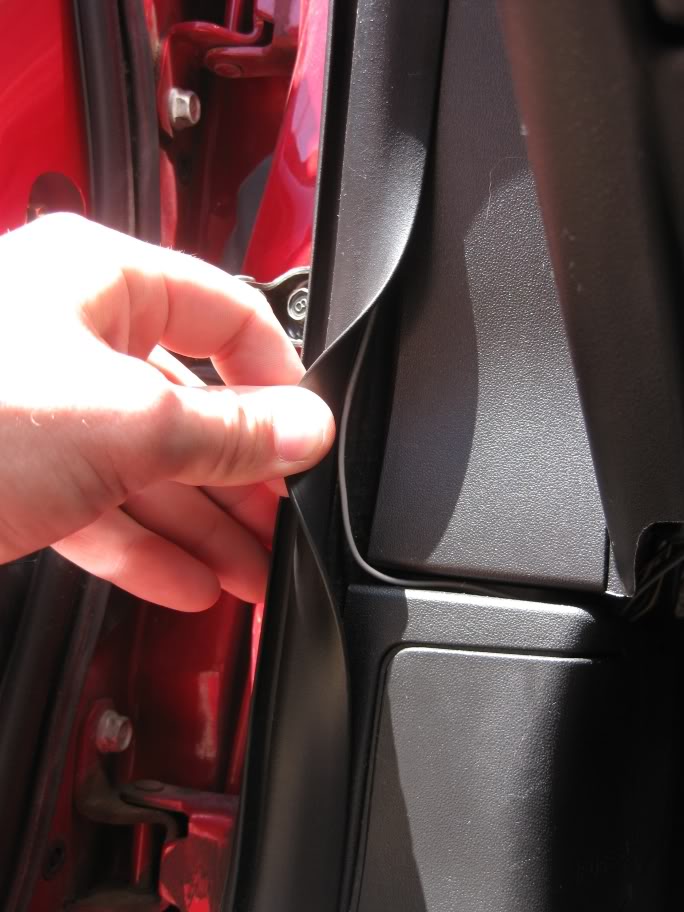
behind the weatherstripping
all the way up the door behind that black stripping
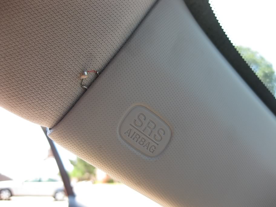
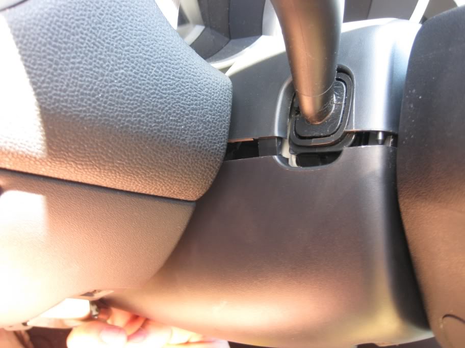
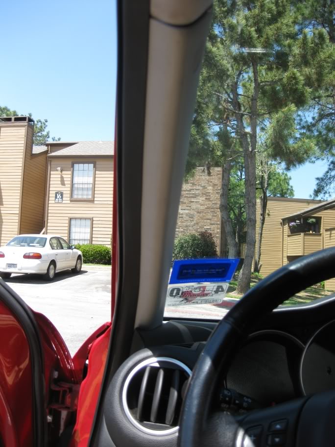
And finally up to where the A pillar cover meets the headliner. This doesn't move at all here and seems to pick up my voice very easily.
Now that the mic and switch line are run to where they need to be, you can run the audio cables to where they need to be. As I previously mentioned, you can just run the cables from your 4conductor cable all the way to the headunit ( if the wires are long enough) or you can solder a set of wires to the headunit seperately and have some form of qucik connect between your new iPhone cable and the headunit wires. You can see in some of my pictures that that's what I have done. The quick connect I used was a 4-pin molex connector because I have like 50 of them.
If you don't already have this done look at this link
The audio, mic, and switch wires are now run and all you have to do is tidy up your console. I snipped out a section of the removable 12V socket piece and ran my wires through there.
I then snipped a corner of the felt cover and slid it around my wires.
If you dont have the AUX jack like I already had, you can run your wires through the console anywhere you want to. I found that 12V removable part is the easiest to deal with though, and if you aren't using the cable it can be stored in that compartment and it won't interfere with your cupholders.
Let me start with I cannot be held responsible for any damage caused to you, or your property.
Now that that's out of the way I'll actually start with what this set-up is and what it will do. The purpose for this setup is to utilize the silent CD method of listening to an aux source, and incorporate the user controls the iPhone's mic/headphone combo provides. So basically when I plug my iPhone into my aux cable instead of only having control of the volume via steering wheel, I will also have control of the song(skipping tracks, pause and play, and answering phone calls) via an external switch akin to the microphone squeeze switch on the iPhone's combo headphones.
Things you will need for this project:
� 1 Quad-contact pushbutton switch (you can get these from radioschack or just break some electronic device you have with a clicky button)
� 10ft. approximately of stranded ~20 gauge wire
� 1 Small microphone (I used the Mic out of the iPhone headphones)
� 1 Four conductor audio jack/cable with 3 sets of wires attached (these are common with A/V cables that come with televisions and dvd players.
� 1 Three conductor audio jack/cable (optional)
� Heat shrink tubing or electrical tape
� Small section of circuit board (optional, but it�s helpful)
� Soldering Iron
� Solder
� Phillips head screwdriver
� Hot glue or epoxy(optional)
� 1 Multimeter
Circuit:
paper-circuit.jpg?t=1240440114
This picture shows that one 4-conductor jack with contacts from tip inward (left, right, ground, microphone) is reduced to a 3-conductor jack (left, right, ground) by splitting the wire corresponding to the innermost contact and ground. This split set of wires will connect to the switch and microphone. The other two sets of wires correspond to the left and right channel audio signals. Those continue to A.) Another jack B.) The stereo C.) A set of L/R wires already soldered to the stereo.
This picture shows how the iPhone�s headphones are wired. In my case the left and right sets of wires proceed to connect to another 3-conductor jack, as in the first picture. In my car I have a L/R audio cable soldered directly to the stereo which runs through the center console and connects to a female 3-conductor audio jack. This is why my L/R wires will re-terminate into a 3-conductor jack and in later pictures you will see the jack next to the 12V socket.
Wiring
First we start with our pushbutton switch. This is represented by the rectangular shape in the previous drawing. The way this switch works is simple. When the button is depressed the 2 signals are shorted together. Using a multimeter you can determine which two legs will be connected when the button is depressed and which two will be connected when the button is not depressed. You will want to solder the microphone�s ground (on the mic) and the microphone ground from the 4conductor jack to two of the legs that connect through the switch when the button is not being pressed. The same principle applies to the positive mic lead and the mic signal from the jack. Now when the button is depressed the microphone signal and the microphone ground will short together. This tells the iPhone that it needs to start/stop/answer a call (one press). * If you use the microphone that came from the iPhone headphones the positive lead is red and the ground lead is green (on the microphone). *
The wiring is a little weird. Your 4conductor jack will be the end you see normally and the rest will be hiding. So let�s start with the 4conductor jack side. From the tip of the jack, as mentioned above, you have L, R, Ground, & Mic. On the other side of the jack there should be 3 sets of wires. One for the left signal and a ground, one for the right signal and a ground, and one for the mic signal and a ground. In my case I split the mic/ground from the L/R wires before tunnelling into the console because of the female jack I already had installed. For me this was about 2 feet of cable (I want to be able to pull the iPhone out of the console while it is still attached so passengers can select music or whatever.) The length of your cable and the length before the split from the L/R wires are up to you.
In the picture above you can see where the L/R split off from the Mic cable and terminate into a 3conductor jack. You can also see the female jack I installed before.
Now from that split, the mic/switch wire runs forward under the console to the left of the shifter, behind the plastic where your right knee rests and up behind the steering wheel. **This totally depends on where you decide you want your switch. I thought about having the button near the seat warmer switches, but if I screwed up with the dremel it would be very apparent to anyone sitting in the car.** That being said, I used about 5 feet of stereo wire for that task. The following pictures are how I routed my wires and where I placed my switch and the mic.
The wires in question are the greay/black stereo wires. The other set of wires goes to the head unit and are the L/R cables. If you choose not to terminate the end of your cable with a 3conductor jack like me then the rainbow cables in my picture would be the L/R audio cables for you.
jump off to the left of the trans. tunnel into the driver's footwell.
Unscrew the 3 screws holding the cover on for the wheel.
snap the left side down and apart
snap the right side down and apart
Now the top(where I drilled a hole for my button and filed out into a square) can be removed.
You can see the portion of breadboard that my pushbutton is on. I put hot glue around the sides of the switch and on top of the breadboard. Even though I don't think the switch would slide, it was a perfect fit for height right there.
From this point I used another 5 or so feet of wire to run the mic somewhere where it could easily pick up my voice. (Instead of soldering the mic leads(green and red) directly to my pushbutton I soldered them to 5 feet of stereo cable and then wired that to the pushbutton)
In the following pictures I show the route I took to get the mic to a good height.
You can see the wire running up to the switch (left) and down toward the mic(right)
Into the crack above teh fuses
behind the weatherstripping
all the way up the door behind that black stripping
And finally up to where the A pillar cover meets the headliner. This doesn't move at all here and seems to pick up my voice very easily.
Now that the mic and switch line are run to where they need to be, you can run the audio cables to where they need to be. As I previously mentioned, you can just run the cables from your 4conductor cable all the way to the headunit ( if the wires are long enough) or you can solder a set of wires to the headunit seperately and have some form of qucik connect between your new iPhone cable and the headunit wires. You can see in some of my pictures that that's what I have done. The quick connect I used was a 4-pin molex connector because I have like 50 of them.
If you don't already have this done look at this link
The audio, mic, and switch wires are now run and all you have to do is tidy up your console. I snipped out a section of the removable 12V socket piece and ran my wires through there.
I then snipped a corner of the felt cover and slid it around my wires.
If you dont have the AUX jack like I already had, you can run your wires through the console anywhere you want to. I found that 12V removable part is the easiest to deal with though, and if you aren't using the cable it can be stored in that compartment and it won't interfere with your cupholders.


Thread
Thread Starter
Forum
Replies
Last Post
jasonrxeight
RX-8's For Sale/Wanted
2
09-30-2015 01:53 PM
nivong
Europe For Sale/Wanted
0
09-02-2015 07:54 AM