How to Scale your MAF for Flash Tuning (Cobb, Hymee)
 04-09-2009, 04:36 PM
#76
U-Stink-But-I-♥-U
iTrader: (1)

Join Date: Mar 2005
Location: 12 o'clock on the Beltway.
Posts: 2,004
Likes: 0
Received 1 Like
on
1 Post
I'll look at it this weekend and update the first post. But to clarify - YOU ONLY correct the MAF at high loads and high RPM's if you are trending by a certain %. All that does is bring your higher MAF voltages closer to actual to be safer UNTIL you actually load up the car and scale them. This is critical in FI because if your whole MAF needs to be scaled by say 10% - and you don't scale the higher points as well then your going to be dangerously lean when you access those points in the MAF.
Not perfect, no. But if you gather much data under various conditions then plot Adjusted Flow vs. Voltage, you will see the a scatter of data, through the middle of which your calibration curve should go. The relative error looks to be about 10%.


 04-09-2009, 06:23 PM
#79

You will never get the open loop AFR to match the targets in the table. To do that you need to get all 3 injectors perfect, you need to get the maf perfect, the engine VE perfect, the fuel VE table perfect, and then deal with the flow disturbances caused by the various ports opening and closing.
the VE table. I was guessing that it should be fairly important as load is calculated based on how much air the engine can flow.
it should have almost as much effect on load as the MAF reading?
04-09-2009, 09:12 PM
#80
U-Stink-But-I-♥-U
iTrader: (1)
Join Date: Mar 2005
Location: 12 o'clock on the Beltway.
Posts: 2,004
Likes: 0
Received 1 Like
on
1 Post
Funny, I am looking at a set of data and from it I can conclude three things:
1) My MAF is decently calibrated. Not complete, but decent.
2) Contrary to stated opinion on another thread, you CAN fit a curve to the Airflow vs MAF volts data. You just have to have the right model/equation. I will give you one hint: Belehradek.
3)You can get your measured AFR close to your expected AFR in OL. There is error, but it is close. With limited data, but in a well calibrated region of flow, at steady state, the average percent error is less than 10% and not statistically different at a p=0.05. Certainly this may change under dynamic conditions, but it is supposed to.
04-09-2009, 09:14 PM
#81
U-Stink-But-I-♥-U
iTrader: (1)
Join Date: Mar 2005
Location: 12 o'clock on the Beltway.
Posts: 2,004
Likes: 0
Received 1 Like
on
1 Post
Srsly. I would love to read folks opinion/results on this table, but it deserves its own thread in the engine management section.
04-09-2009, 09:19 PM
#82

3)You can get your measured AFR close to your expected AFR in OL. There is error, but it is close. With limited data, but in a well calibrated region of flow, at steady state, the average percent error is less than 10% and not statistically different at a p=0.05. Certainly this may change under dynamic conditions, but it is supposed to.
04-09-2009, 10:01 PM
#83
hymee's explanation of VE and load_abs are a good reference. I know when the VE tables are expanded for FI they are flat and possibly need tuning for accurate loads?
04-09-2009, 10:05 PM
#84
U-Stink-But-I-♥-U
iTrader: (1)
Join Date: Mar 2005
Location: 12 o'clock on the Beltway.
Posts: 2,004
Likes: 0
Received 1 Like
on
1 Post
Under dynamic conditions (RPM changing with time, throttle changing with time, ) all bets are off. Read exactly what I wrote. It is an hypothesis, currently, and I will try to disprove it as best I can, but I would bet a six-pack of good beer that in OL at steady state (no change in speed, throttle) measured AFR will match expected.
04-10-2009, 06:59 PM
#86
Dongbag extrordinare

Join Date: Nov 2004
Location: Away from the fruits of my labor
Posts: 1,090
Likes: 0
Received 0 Likes
on
0 Posts
04-10-2009, 07:06 PM
#88
Dongbag extrordinare
Join Date: Nov 2004
Location: Away from the fruits of my labor
Posts: 1,090
Likes: 0
Received 0 Likes
on
0 Posts
I would only agree with this statement if you are running n/a with stock injectors and stock exhaust, etc. With boost and all your other mods, the VE of the motor is radically different. I believe that the Evo method of tuning would work fine since your "target" lambda under OL fueling is now meaningless with forced induction. If I am correct then you guys can skip high load/rpm MAF scaling headaches. Just compensate in your OL fuel maps.
However, since the our stock scaling only goes to 365 g/s, anyone running over 9lbs. of boost has to scale theirs to account for the extra air.
-Yambo
04-10-2009, 07:12 PM
#89
Dongbag extrordinare
Join Date: Nov 2004
Location: Away from the fruits of my labor
Posts: 1,090
Likes: 0
Received 0 Likes
on
0 Posts
I changed the numbers at the bottom of the y-axis(using ATR) to reflect my new maximum loads under boost. Then I did a few-hundred data logs, slightly changing the VE in boost across the entire rpm range untill I started seeing my target AFRs. I actually came pretty damn close, and I never touched the MAF scaling.
This is not to say it will not work, just that I did this because when I tried only scaling the MAF, the only way I could get my target AFRs was to create unrealistic numbers(400+ g/s w/only 8lbs of boost) on the upper end of the scale.
I still plan on going back to the MAF now that I am comfortable with the VE table.
-Yambo
04-11-2009, 12:16 PM
#90
U-Stink-But-I-♥-U
iTrader: (1)
Join Date: Mar 2005
Location: 12 o'clock on the Beltway.
Posts: 2,004
Likes: 0
Received 1 Like
on
1 Post
This is also correct, IMHO. I have found that playing with the VE for the boosted ranges are more productive than scaling the MAF.
However, since the our stock scaling only goes to 365 g/s, anyone running over 9lbs. of boost has to scale theirs to account for the extra air.
-Yambo
However, since the our stock scaling only goes to 365 g/s, anyone running over 9lbs. of boost has to scale theirs to account for the extra air.
-Yambo
Post up exactly what you did so that you can at least put some value to your words. Again, dont take this the wrong way. I am looking at data right now, and will post it within the next few days that completely contridicts stated "fact" in a lot of posts, not just in this thread. Specifically, that expected AFR predicts measured AFR with a correlation of 0.9 or better at steady state, that you CAN use the proper equation (an equation built on first principles) to fit your adjusted flow to maf volts and use the parameters to build your new maf calibration (a fact that leads me to state that MAF calibration can be automated in Excel,) and finally, that the GReddy MAF housing CAN be with the proper physical set up (though I agree that it is not the best thing to use.)
04-11-2009, 01:15 PM
#91
Dongbag extrordinare
Join Date: Nov 2004
Location: Away from the fruits of my labor
Posts: 1,090
Likes: 0
Received 0 Likes
on
0 Posts
No worries. I am not trying to convince anyone that I am right. Just throwing my "limited" experience out there. I have created well over 50 maps for my FI RX8 at this point using the ATR software. My posts are only meant to assist those using said software, since I do not have any experience using other tuning devices/means.
I guess I should have been a little more precise, knowing members of this forum, but I'll try to correct that now. When I stated that using VE seemed to be more productive, what I meant was tuning with VE was the ONLY way I could get consistent AFRs when boosting across then entire rpm range. I don't have any maps, charts, data logs, etc to show this. So sorry.
None of this was meant to say scaling the MAF isn't necessary. I freely admit that I tried several times and never got the results I wanted. I am reading this thread to hopefully learn something about it.
Good luck with your MAF scaling spreadsheet. If you want someone to try it to prove it actually works, I'll be more than willing to.
04-11-2009, 01:21 PM
#92
I love you guys.... but good grief your making this a lot harder that it needs to be.
You guys are jumping the gun - stop messing with stuff. Go one step at a time.... if you are getting turbulence then that is an intake issue - but barring that, you can scale the MAF - it is just tedious.
Keep in mind it is slow... so you have to get it at one consistant voltage for 20 seconds or more to get the AFR's to stabilize. This is hard to do at higher loads without a dyno.
04-15-2009, 10:12 PM
#93
U-Stink-But-I-♥-U
iTrader: (1)
Join Date: Mar 2005
Location: 12 o'clock on the Beltway.
Posts: 2,004
Likes: 0
Received 1 Like
on
1 Post
Just wanted to update with some research that i have done while my car has been down (changing out injectors.)
I did some looking around to try and derive a function that could describe the voltage needed to maintain a temperature in a wire when air is passing
it. I did enough to understand the problem, but as you can imagine, this has been studied. In fact, there are patented systems that can
automatically calibrate a MAF when another system determines that the current calibration is out of spec. These systems are built around the
parameterized power equation
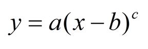
where y is air flow, x is voltage and a, b and c are non-linear parameters controling the shape of the graph. The fitting could be any non-linear
iterative process. The output of the parameters are then be used to draw a new calibration.
In fact, I used this process to draw my own MAF calibration. I first generated Mass air, MAF volts and measured AFR and calculated the adjusted Mass air vs. MAF volts curve through the process above. A curve fit through this adjusted mass air data is the new calibration. I have attached a graph of my data showing my previous calibration curve in green, which is the stock calibration adjusted downward by 14%, my data that I used for the fit in open black points and my fit of the parameterized equation above in red. I have also included data in red open circles, which are not included in the analysis. THese points are in the graph representing higher flows but were collected when the AFRs were below 11.1, the limit of the stock wbo2. They are slightly higher than the calibration as I used a higher measured AFR than the actual AFR (which was in the mid 10s)
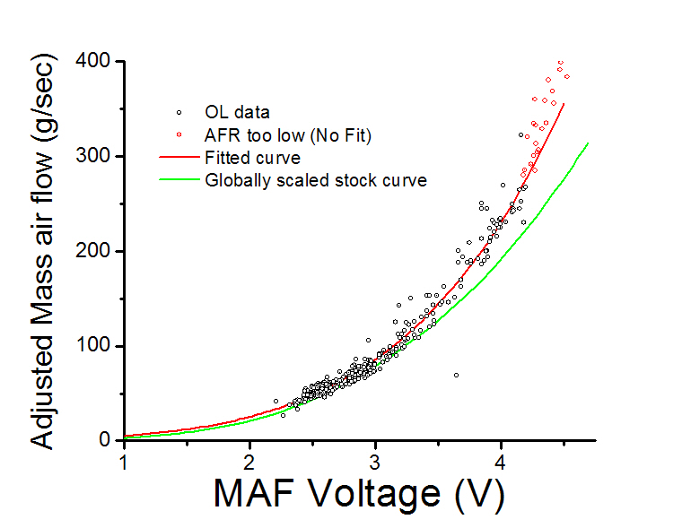
I only got a limited set of data with this calibration before I figured out I had installed injectors that could potentially damage my pcm. I will likely install with the AEM intake so I will not get full data on the greddy intake. Nevertheless, I did find that my expected AFR predicted my measured AFR with an R-value of 0.82 (essentialy saying that 82% of the variability of the measured AFR can be attributed to changing expected AFR.)
I did some looking around to try and derive a function that could describe the voltage needed to maintain a temperature in a wire when air is passing
it. I did enough to understand the problem, but as you can imagine, this has been studied. In fact, there are patented systems that can
automatically calibrate a MAF when another system determines that the current calibration is out of spec. These systems are built around the
parameterized power equation
where y is air flow, x is voltage and a, b and c are non-linear parameters controling the shape of the graph. The fitting could be any non-linear
iterative process. The output of the parameters are then be used to draw a new calibration.
In fact, I used this process to draw my own MAF calibration. I first generated Mass air, MAF volts and measured AFR and calculated the adjusted Mass air vs. MAF volts curve through the process above. A curve fit through this adjusted mass air data is the new calibration. I have attached a graph of my data showing my previous calibration curve in green, which is the stock calibration adjusted downward by 14%, my data that I used for the fit in open black points and my fit of the parameterized equation above in red. I have also included data in red open circles, which are not included in the analysis. THese points are in the graph representing higher flows but were collected when the AFRs were below 11.1, the limit of the stock wbo2. They are slightly higher than the calibration as I used a higher measured AFR than the actual AFR (which was in the mid 10s)
I only got a limited set of data with this calibration before I figured out I had installed injectors that could potentially damage my pcm. I will likely install with the AEM intake so I will not get full data on the greddy intake. Nevertheless, I did find that my expected AFR predicted my measured AFR with an R-value of 0.82 (essentialy saying that 82% of the variability of the measured AFR can be attributed to changing expected AFR.)
04-16-2009, 10:58 AM
#95
Registered

Join Date: Aug 2007
Posts: 29
Likes: 0
Received 0 Likes
on
0 Posts
Just wanted to update with some research that i have done while my car has been down (changing out injectors.)
I did some looking around to try and derive a function that could describe the voltage needed to maintain a temperature in a wire when air is passing
it. I did enough to understand the problem, but as you can imagine, this has been studied. In fact, there are patented systems that can
automatically calibrate a MAF when another system determines that the current calibration is out of spec. These systems are built around the
parameterized power equation
where y is air flow, x is voltage and a, b and c are non-linear parameters controling the shape of the graph. The fitting could be any non-linear
iterative process. The output of the parameters are then be used to draw a new calibration.
In fact, I used this process to draw my own MAF calibration. I first generated Mass air, MAF volts and measured AFR and calculated the adjusted Mass air vs. MAF volts curve through the process above. A curve fit through this adjusted mass air data is the new calibration. I have attached a graph of my data showing my previous calibration curve in green, which is the stock calibration adjusted downward by 14%, my data that I used for the fit in open black points and my fit of the parameterized equation above in red. I have also included data in red open circles, which are not included in the analysis. THese points are in the graph representing higher flows but were collected when the AFRs were below 11.1, the limit of the stock wbo2. They are slightly higher than the calibration as I used a higher measured AFR than the actual AFR (which was in the mid 10s)
I only got a limited set of data with this calibration before I figured out I had installed injectors that could potentially damage my pcm. I will likely install with the AEM intake so I will not get full data on the greddy intake. Nevertheless, I did find that my expected AFR predicted my measured AFR with an R-value of 0.82 (essentialy saying that 82% of the variability of the measured AFR can be attributed to changing expected AFR.)
04-17-2009, 03:46 PM
#96
Dongbag extrordinare
Join Date: Nov 2004
Location: Away from the fruits of my labor
Posts: 1,090
Likes: 0
Received 0 Likes
on
0 Posts
Holy crap. That was a tough read. Care to break that down barney style? The part I am most interested in is the device/software that can calibrate your MAF for you.
-Yambo
-Yambo
04-17-2009, 04:55 PM
#97
I only got a limited set of data with this calibration before I figured out I had installed injectors that could potentially damage my pcm. I will likely install with the AEM intake so I will not get full data on the greddy intake. Nevertheless, I did find that my expected AFR predicted my measured AFR with an R-value of 0.82 (essentialy saying that 82% of the variability of the measured AFR can be attributed to changing expected AFR.)
there is no denying that you can (can't
 what was I thinking) scale the MAF based on AFR however it is interesting where the relationship between AFR and MAF flow breaks down. I will hazard a guess that the calibration at high flows falls over due to a map that has been extended for high loads hasn't been tuned. possibly the VE map? these maps aren't tuned passed 125%-130% load in most cases.
Last edited by rotarenvy; 04-17-2009 at 11:28 PM. Reason: stupidity
 04-17-2009, 09:42 PM
#99
U-Stink-But-I-♥-U
iTrader: (1)
Join Date: Mar 2005
Location: 12 o'clock on the Beltway.
Posts: 2,004
Likes: 0
Received 1 Like
on
1 Post
there is no denying that you can't [?] scale the MAF based on AFR however it is interesting where the relationship between AFR and MAF flow breaks down. I will hazard a guess that the calibration at high flows falls over due to a map that has been extended for high loads hasn't been tuned. possibly the VE map? these maps aren't tuned passed 125%-130% load in most cases.
What I think you stated is my guess as well. That there are tables that increasingly interact with the OL tables at higher loads. Somehow, these tables do not interact at low acceleration, low tip-in, or low load. The problem is that in the ATR there is no explanation as to how these tables interact with each other. It is reasonable to wonder if these are availible in the pro version as we know that there are some programing restrictions in ATR. I am not complaining as the ATR is free. I just wonder what we are missing. These interactions can be figured out tho. It will just take many tanks of gas at jail-time speeds.
Exactly. WOT runs prolly should not be used to scale the MAF. (Tuning is a different question) Very slow, steady increases in rpm are ok, something less than 10rpm/sec. Anything faster and the wbo2 cant keep up sufficiently for accurate data. Plus the Throttle fuel gear table and, I believe, the Fuel VE table begin to add fuel over the OL maps. All this will **** with your relationship between your measured and expected AFR and screw up the cal.
04-17-2009, 09:53 PM
#100
U-Stink-But-I-♥-U
iTrader: (1)
Join Date: Mar 2005
Location: 12 o'clock on the Beltway.
Posts: 2,004
Likes: 0
Received 1 Like
on
1 Post
As for the software, I am assuming that you want to do this yourself? Do you have MS excel? That is what I and everyone else based most of this on. I use OriginPro for all my other higher-end analysis but it is kinda expencive just for playing around. You can download addons for Excel to do most stuff and Excel can be macroed to run Levenburg-Marquart nl fitting. The only problem is that you cant really trust Excel to spit out "true" numbers. It has to ALWAYS be checked as there are old, inherent errors in the excel algorithms that MS has famously ignored for more than 13 years.
I should note that you dont HAVE to do this. It was just fun to do. You can make your calibration by hand as easy or easier than curve fitting. You just need to calculate "adjusted flow." Did you understand that part of the above?

