How to Scale your MAF for Flash Tuning (Cobb, Hymee)
 03-26-2009, 12:38 AM
#26

The instantaneous MAF value isn't useful.
Its trended.
That is why its non-linear out put is useable.
You can calibrate any intake you want. Just be prepared to fight with it and still come out with an unsatisfactory output.
The "Stock Style" MAP is the latest Mazda flash, unaltered.
The injector scaling is voodoo. Because latency affects it and delivery is a variable, not knowing the MAF output is going to make it impossible to know the proper scaling.
So, just pull it out of your butt and be prepared to address it again later.
I have about 400 flashes on my PCM and counting.


 03-26-2009, 07:01 AM
#30
U-Stink-But-I-♥-U
iTrader: (1)

Join Date: Mar 2005
Location: 12 o'clock on the Beltway.
Posts: 2,004
Likes: 0
Received 1 Like
on
1 Post
Mucho thanks.
I can imagine how the output of a moving average or autocorrelation function could function as a sort of vector, but you would still need some locally invertable MAF scale at startup. Also, if, as you say the MAF scale is non-invertable over a significanly large section of the curve, then if the voltage drops yet the flow increases, you would have to know WHICH local max you just passed. IF that is true, that is a pretty remarkable computer.
But WAIT! Imagine that you are the PCM. You know where you are in the local area of the curve because you have been following voltage from some unambiguous startup value. Now you are at the peak of some local maximum. No matter what happens next, the voltage is going to drop. Lets say that the flow increases and the voltage drops to the right of the local maximum. How do you know, as the PCM, that you fell off the local max to the right. you could have very well dropped off to the left and needed less fuel. Ah! but as the PCM, you also know TP and a host of other outputs. I am begining to see how the interactions become complecated....
03-26-2009, 09:40 AM
#31
Registered
iTrader: (1)

Join Date: May 2003
Location: PA
Posts: 3,754
Likes: 0
Received 0 Likes
on
0 Posts
...just because I didn't see this in the thread...
If your changing the size of your MAF tube and therefore need to recalibrate the maf curve the starting point should be to multiply the old curve the the ratio of the new and old maf tube areas. In other works your starting scale factor would be...
scale % = ((new tube radius^2/old tube radius^2)-1)*100
This is based on assumptions you have fully laminar flow, the maf remains in the same relative position in the tube, and your not changing air properties or creating turbulence somewhere....
03-26-2009, 12:36 PM
#32
Overall my AFRs are pretty damn good with just maf scaling done but i would like to richen up a few peaks for those times the LTFT wanders around a bit .
03-28-2009, 12:57 AM
#33

if the maf isn't just a smooth curve it sounds like Kane's software would work well finding the average? even if it isn't a smooth curve all the time it can obviously be approximated by one.
I reckon the MAF would do stuff all on cranking. there would be cold start parameters in there instead of calculated loads. once it's running then it would use the MAF
I reckon the MAF would do stuff all on cranking. there would be cold start parameters in there instead of calculated loads. once it's running then it would use the MAF
03-31-2009, 04:03 AM
#36
I can tell you i made huge changes on the other two maps and they did absolutely nothing . The map i had thought was gear 1-2 i had not touched much because I was concentrating on getting 3rd gear right initially so was working on what i thought was the 3-4 map mostly .
As soon as i started playing with map 1 it affected AFRs in ALL the gears .
PCM is N3YMEC which is from the first year of JDM production ....
04-02-2009, 04:59 PM
#37
Guest
Posts: n/a
Maybe there is something wrong .
I can tell you i made huge changes on the other two maps and they did absolutely nothing . The map i had thought was gear 1-2 i had not touched much because I was concentrating on getting 3rd gear right initially so was working on what i thought was the 3-4 map mostly .
As soon as i started playing with map 1 it affected AFRs in ALL the gears .
PCM is N3YMEC which is from the first year of JDM production ....
04-03-2009, 10:50 AM
#39
Registered User

Join Date: May 2006
Location: Montreal, Canada
Posts: 145
Likes: 0
Received 0 Likes
on
0 Posts
Just a simple stupid question. In order to scale the MAF, I guess that I will have to create a MAP that force the ECU to always put 14,70 AFR into the engine ?
Is it safe to do so ? My map is ready with open loop and closed loop set at 14,7. I'm not planning on running at high load and high RPM with that map but I'm still a bit worried about hurting the engine with that MAP.
Did I understood your recomendations right ? I have the REVI intake and currently my LFT is at +11, I guess that I need a MAF calibration for that reason.
Thanks,
04-03-2009, 05:27 PM
#40
I'm a bit worried about the lamda 1 instructions also.
popping the rear o2 sensor? (check which one is correct) is supposed to force open loop.
then for the different lambdas use different gears. the lamda 1 area changes for gears 1-2, 3-4, 5-6 so you can probably avoid changing the maps and still hit a large portion of the maf range.
also as for FI instructions you really just need to reference back to the lambda target your map is set for. it should be hitting what ever lambda it is set for at the load/rpm.
04-08-2009, 12:18 AM
#42
U-Stink-But-I-♥-U
iTrader: (1)
Join Date: Mar 2005
Location: 12 o'clock on the Beltway.
Posts: 2,004
Likes: 0
Received 1 Like
on
1 Post
Detailed and Corrected Scaling Procedure for MAF Calibration
I believe that the majority of the discussion with regards to the DETAILS of scaling the MAF are in error at some level. I want to post my methods of scaling my MAF calibration.
I have not yet seen either an error free or full, detailed description of the MAF scaling here. It is not my intention to call these errors out; however, I will point out that the majority of the errors lie in the very fine details of calculating a correction. They may have been written in haste and escaped into the posts this way, or the poster had no ******* idea what they were talking about. Either way, if you attempt to use these methods, the results are garbage.
The importance of scaling the MAF has been discussed many times, but it deserves repeating. If your MAF is not scaled correctly, and you make alterations to any map, you are NOT tuning. This sounds like semantics, and in a way, it is. If you define “tuning” as making logical adjustments to maps to provide optimum, power, response, transition and safety, then you CAN NOT TUNE WITHOUT A PROPERLY SCALED MAF. Without the proper scaling you can make NO logical adjustment. You can only hunt and peck and hope you get somewhere. I did not come up with this conclusion; I only repeat it because I came to the same conclusion after hours of careful consideration of multiple data that all point, inexorably, to this terminus.
When considering the MAF system, there are some defined concepts to separate. First is air flow. There are THREE air flow numbers to conceptualize. First is true airflow. This is the number we wish to know. Then there is measured airflow. This is the number that we arrive at through the workings of the MAF. They are two different numbers even when they are equivalent (which we wish them to be.) Finally, relevant to this discussion is Adjusted airflow, which is measured airflow, to which we have applied a correction factor. What we want to do is determine if our MAF is reporting measured airflow that is very close to the true value, and we will make corrections through adjusted airflow.
When the engine ingests fuel, and a sub-stoichiometric amount of air is concomitantly consumed, excess fuel is expelled. We have a relatively direct measure of the ratio of how much fuel relative to the amount of oxygen that is consumed (λ). If the computer thinks that more air is entering the engine than what actually is, the computer will mistakenly add too much fuel, creating a rich condition and vice versa. We can evaluate the factor by which the computer made a mistake by comparing the output AFR to the expected AFR. This factor is correctly evaluated as (measured AFR-expected AFR)/expected AFR.
This simple equation can be used as the key to iteratively seeking the correct MAF scaling at any achievable flow.
This calculated value is the unitless correction that can be applied to your measured flow to appropriately scale your MAF calibration at the relevant voltage. Because LOAD is a component in this calculation (as you will see), it is possible that a single iteration of this method will only bring you closer to a correct scale. Multiple iterations may be required.
So lets see this calculation in action. My personal example of scaling the MAF started with my stubbornness to remove my Greddy MAF housing. I still believe that this housing can work with the appropriate physical set up, but I have put an AEM CAI on order to play with as well. I believe that my starting map is scaled to the stock intake box. I believe that this box has an inner diameter in the housing of 3 and 3/8”, but I don’t have one handy to measure. The Greddy inner diameter can be approximated to 3”, but the geometry is somewhat complex.
I noticed that while I could reasonably hit expected AFR at low and higher loads, at medium loads I was incredibly rich. So I decided to scale the entire MAF curve down by about 14%. These curves are plotted in the attached graph as open symbols.
When I did this, although I could target some AFR, I got very lean at load. The reason, I believe, is that scaling by a factor can only be correctly done by parameterizing said factor into the model that controls the shape of the curve. Just moving the curve up by a factor does not take into account the physical model at hand.
Nevertheless, empirical adjustment of the MAF curve is much more accurate and much more useful. The details are such:
Log data IN OPEN LOOP. There are ways to ensure you are in OL, but it is verifiable by checking to make sure that in the areas of interest in your logs, that LTFT-STFT=0. Make sure that when you log your data (Load, RPM, Mass air, MAF volts, AFR) that you have allowed the trims to settle and that you are at operating temp. I personally start the car, bring it to temp for 10 minutes, shut down for a few minutes then restart and drive for 10 more minutes.
Now the process of generating a correction is easy; using your open loop fuel table, look up the expected lambda for each data point using RPM and load as variables. This can be done by hand, but it is tedious. I discovered an Add-on for Excel at http://www.xlxtrfun.com/XlXtrFun/XlXtrFun.htm that allows you to use an indexed fuel table (or a matrix, though I have not tried it) to interpolate (pull-out) expected lambda using your measured load and rpm as variables. This is a very slick way to do this, IMO.
Once you have sets of expected and measured lambda at various measured flow, you can calculate your correction factor (as above), add 1, multiply to measured flow to generate corrected or adjusted flow vs MAF voltage (Plotted in RED). I intend to either fit a single exponential to this adjusted flow and use the parameters to generate an interpolated curve or hand-fit to generate my newly scaled MAF curve. Either way will work. Using this method you can populate all physically achievable areas of the curve. This is recommended.
If you look at my adjusted data, you will see that while some of the curve needs adjustment, some areas do not. That is why I was getting weird results; i.e., rich in some spots, lean in others.
In any case, the only real advancement here is the ability to “pull-out” expected AFR from a fuel table instead of doing it by hand using readily available software and add-ons. I also believe that this method is sufficiently detailed to CORRECTLY scale the MAF calibration.
[FONT=Arial][SIZE=3][COLOR=#000000]Let me know if this clears up any issues, if there are further issues or if any files or screenshots would be helpful.
The following users liked this post:
miro279 (06-24-2022)
04-08-2009, 09:02 AM
#45
U-Stink-But-I-♥-U
iTrader: (1)
Join Date: Mar 2005
Location: 12 o'clock on the Beltway.
Posts: 2,004
Likes: 0
Received 1 Like
on
1 Post
Yeah, I actually wanted to post this in it, but didnt want to be insulting. Your method is PERFECTLY fine but there are some math errors in it (in the downloadable excel sheet) that I wanted to correct. If you want, I can just post this over there and delete this. No reason to make clutter. Your thread started me off, so it only makes sence.
04-08-2009, 09:24 AM
#46
Registered
iTrader: (1)
Join Date: May 2003
Location: PA
Posts: 3,754
Likes: 0
Received 0 Likes
on
0 Posts
i tried this method about a year ago with decent results...
it gets complicated though because different gears had different lambda's due to different fuel maps and the resultant afr error %s were different. You also assume in this method that your fuel injectors are scaled properly which may or may not be a good assumption.
BTW - the black text is really hard to read if you have a dark theme on this site. Its better to use the default color.
04-08-2009, 09:46 AM
#47
U-Stink-But-I-♥-U
iTrader: (1)
Join Date: Mar 2005
Location: 12 o'clock on the Beltway.
Posts: 2,004
Likes: 0
Received 1 Like
on
1 Post
I forgot about the text thing. I wondered why it looked funny. I just copied and pasted from Word. If Kane wants me to post over on his thread. I will correct it. (or maybe we can get a mod to merge them and save me the effort.  )
)
I have attached a screenshot of the excel sheet of the process. It includeds the addon mentioned.
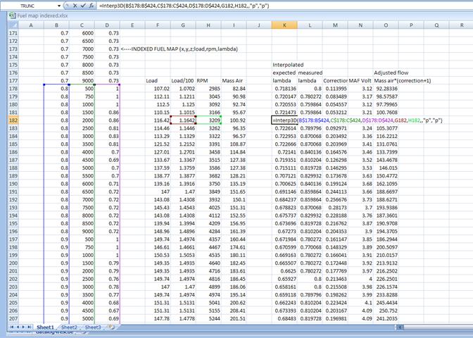
The gearing isnt an issue because you can set up an equation to calculate which gear you are in from speed and rpm. This way, the excel sheet can choose which map to draw the expected lambda. That is easy.
The injector issue is a problem that I have not yet evaluated experimentally. Depending on how the injectors are staged, it is possible that this calibration proceedure eliminates fine tuning the injector scaling. I will get to that later, but the process to determine the exact injector scale should be analogous to this one, only with using injector duty cycles.
)I have attached a screenshot of the excel sheet of the process. It includeds the addon mentioned.
The gearing isnt an issue because you can set up an equation to calculate which gear you are in from speed and rpm. This way, the excel sheet can choose which map to draw the expected lambda. That is easy.
The injector issue is a problem that I have not yet evaluated experimentally. Depending on how the injectors are staged, it is possible that this calibration proceedure eliminates fine tuning the injector scaling. I will get to that later, but the process to determine the exact injector scale should be analogous to this one, only with using injector duty cycles.
04-08-2009, 11:23 AM
#48
Registered
iTrader: (1)
Join Date: May 2003
Location: PA
Posts: 3,754
Likes: 0
Received 0 Likes
on
0 Posts
If you want my 2 cents, ignore the data from first and second gears if you are anywhere close to WOT as the latency from the O2 sensor becomes rediculous and somewhat random. An easy why of checking it it before doing a WOT run, start logging, get off the gas pedal completely to do a fuel cut, watch for the afr to go to 20, then do the WOT run and at the end sharply get off the gas to go into the fuel cut. Look at the data and if you have the throttle position logged you'll probably find a latency at the beginning of the run of 1-2 data points (~ .2 sec) and by the end 5-6 data points (~.5 sec) which is enough to be off by a good 1,000+ rpms in second gear.
I found doing my own tuning I had a strange blip around 7000 -7250 rpms in every run in second gear that would not respond to changing the fuel tables in that area. I finally figured out it was occuring at 6250 rpms with the APV opening and suddenly I was able to tune the problem away by changing the map down there. Perhaps this weekend I will get some time to put together how I came up with my final tune...
I found doing my own tuning I had a strange blip around 7000 -7250 rpms in every run in second gear that would not respond to changing the fuel tables in that area. I finally figured out it was occuring at 6250 rpms with the APV opening and suddenly I was able to tune the problem away by changing the map down there. Perhaps this weekend I will get some time to put together how I came up with my final tune...
04-08-2009, 02:53 PM
#50
Registered
iTrader: (1)
Join Date: May 2003
Location: PA
Posts: 3,754
Likes: 0
Received 0 Likes
on
0 Posts
I was hell bent at being super scientific when I started my tuning and have every change backed up with number - then i discovered this and realized the changed needed to really be made with an artistic brush


