How Kane Tunes an FI Renesis - Turbo, Ported, Ceramic Seals
 12-29-2009, 03:27 PM
#1

How Kane Tunes an FI Renesis - Turbo, Ported, Ceramic Seals
Well now is as good a time as any to start this thread off.
First A Few Caveats
* I am using the Hymee Pro Tuner Software
* I am logging / monitoring with the Hymee Live USB
* I have a second Wideband O2 for a reality check against stock
* I have a log-able Fuel Pressure Gauge with a peak and low FP warning light - this way I can log if I have any dips in Fuel Pressure while boosting.
* My motor is a ported, 1 Piece ceramic sealed engine - so your results may vary... the biggest drawback I've seen is just low idle speeds cause sealing issues (which is why Mazda went with a 2 piece seal in the first place).
* I have 189 Miles on the new engine to date.
* I am using the AEM air intake MAF housing along with a custom CAI set-up
* My turbo is the GT3071R
* All calculations and tuning is being done in Baseline my custom tuning software... so good bad or ugly I am going to attempt to tune this entire car scientifically.
Now on to the initial map:
With a fairly custom engine, I was unsure exactly how to start - but I KNEW the first thing to do was flow test the injectors in order to take them out of the equation. This way all my Fuel Trims and MAF scaling are against an known standard. I also raised my idle to 1000 RPMS due to the poor compression I was getting at 750 - this is based on the old school ported ceramic rotaries... and worked for me - so whether it's good or bad is up to you to decide.
That being said - I took Hymee's Base Map, my tuning results from J.Cab, Bobby, My old engine, etc to come up with a basemap to get things started. Now DO AS I SAY NOT AS I DO - since you should always tune cruise first and not idle - but my OCD got me and I had to f^&K with the idle too....
So I scaled my injectors based on my flow test:
P1's are now 407.693 = 320cc
Secondaries are now 500.978 = 400cc
P2's are now 1027.806 = 820cc
Then I setup the load to 200% and the Forward Loop Gain aka fuel VE% all to 1 to eliminate that as a variable. I also upped the OMP and turned the fans on sooner - standard first map stuff.
Then I loaded the map - and captured idle MAF data, 2500, 3000, 3500, 4000 RPM data to see where my variances were in cruise with the factory MAF scale.
Since the Hymee doesn't have the closed loop tables YET - I had to massage the STFT into the equation in order to get a good comparison.... with the Access Port I normally turn the Closed Loop off so you can just work on the MAF scale.
My results are as follows.
From 2500 RPM - MAF variance + STFT = 12.555%
From 3000 RPM - MAF variance + STFT = 12.83%
From 3500 RPM - MAF variance + STFT = 4.34%
From 4000 RPM - OPEN LOOP MAF var. = 3.2%
So I scaled the MAF accordingly and re-logged.
From 2500 RPM - MAF variance + STFT = 3.01%
From 3000 RPM - MAF variance + STFT = 1.00%
From 3500 RPM - MAF variance + STFT = 1.65%
From 4000 RPM - OPEN LOOP MAF var. = 3.2%
My open loop didn't change - this is due to pegging the AFR gauge - so it's gonna take a few passes to work that one out. But basically in one round of tuning I took care of all my Cruise areas...... after 3-4 drive cycles; my LTFT is 0%. Crazy I know, we will see if it changes.
As for my idle - it's better but not perfect - I patched it by flat-lining the MAF some; and I need to work out the turbulence issue as well as dedicated idle tuning.
Now that the base map is about done - I need to drive a few hundred miles on it and start in on the boosted and WOT mapping.


Leading and Trailing Timing

Base Fueling for Gears 1-3

Base Fueling for Gears 4-6

Baseline MAF Scaling information from 2500 RPM cruise.
Here is the MAF scale so far - I am scaling the curve up as I need to based on the findings in my logs - but I haven't gotten there yet to verify.

First A Few Caveats
* I am using the Hymee Pro Tuner Software
* I am logging / monitoring with the Hymee Live USB
* I have a second Wideband O2 for a reality check against stock
* I have a log-able Fuel Pressure Gauge with a peak and low FP warning light - this way I can log if I have any dips in Fuel Pressure while boosting.
* My motor is a ported, 1 Piece ceramic sealed engine - so your results may vary... the biggest drawback I've seen is just low idle speeds cause sealing issues (which is why Mazda went with a 2 piece seal in the first place).
* I have 189 Miles on the new engine to date.
* I am using the AEM air intake MAF housing along with a custom CAI set-up
* My turbo is the GT3071R
* All calculations and tuning is being done in Baseline my custom tuning software... so good bad or ugly I am going to attempt to tune this entire car scientifically.
Now on to the initial map:
With a fairly custom engine, I was unsure exactly how to start - but I KNEW the first thing to do was flow test the injectors in order to take them out of the equation. This way all my Fuel Trims and MAF scaling are against an known standard. I also raised my idle to 1000 RPMS due to the poor compression I was getting at 750 - this is based on the old school ported ceramic rotaries... and worked for me - so whether it's good or bad is up to you to decide.
That being said - I took Hymee's Base Map, my tuning results from J.Cab, Bobby, My old engine, etc to come up with a basemap to get things started. Now DO AS I SAY NOT AS I DO - since you should always tune cruise first and not idle - but my OCD got me and I had to f^&K with the idle too....
So I scaled my injectors based on my flow test:
P1's are now 407.693 = 320cc
Secondaries are now 500.978 = 400cc
P2's are now 1027.806 = 820cc
Then I setup the load to 200% and the Forward Loop Gain aka fuel VE% all to 1 to eliminate that as a variable. I also upped the OMP and turned the fans on sooner - standard first map stuff.
Then I loaded the map - and captured idle MAF data, 2500, 3000, 3500, 4000 RPM data to see where my variances were in cruise with the factory MAF scale.
Since the Hymee doesn't have the closed loop tables YET - I had to massage the STFT into the equation in order to get a good comparison.... with the Access Port I normally turn the Closed Loop off so you can just work on the MAF scale.
My results are as follows.
From 2500 RPM - MAF variance + STFT = 12.555%
From 3000 RPM - MAF variance + STFT = 12.83%
From 3500 RPM - MAF variance + STFT = 4.34%
From 4000 RPM - OPEN LOOP MAF var. = 3.2%
So I scaled the MAF accordingly and re-logged.
From 2500 RPM - MAF variance + STFT = 3.01%
From 3000 RPM - MAF variance + STFT = 1.00%
From 3500 RPM - MAF variance + STFT = 1.65%
From 4000 RPM - OPEN LOOP MAF var. = 3.2%
My open loop didn't change - this is due to pegging the AFR gauge - so it's gonna take a few passes to work that one out. But basically in one round of tuning I took care of all my Cruise areas...... after 3-4 drive cycles; my LTFT is 0%. Crazy I know, we will see if it changes.
As for my idle - it's better but not perfect - I patched it by flat-lining the MAF some; and I need to work out the turbulence issue as well as dedicated idle tuning.
Now that the base map is about done - I need to drive a few hundred miles on it and start in on the boosted and WOT mapping.
Leading and Trailing Timing
Base Fueling for Gears 1-3
Base Fueling for Gears 4-6
Baseline MAF Scaling information from 2500 RPM cruise.
Here is the MAF scale so far - I am scaling the curve up as I need to based on the findings in my logs - but I haven't gotten there yet to verify.
Last edited by Kane; 12-29-2009 at 03:45 PM.
 12-29-2009, 03:27 PM
#2
Ok, so with my injectors good to go - time to keep going with the MAF, including WOT and boosted areas.
Starting small - keep in mind my Fuel VE% are all at 1, so every Baseline Run gets a double check to see if my injectors are messing up or if it is my MAF.


As you can see, I am not seeing a big enough trend in my 3D map to warrant me messing with my fuel VE% yet.... so I'll edit the MAF again, and then go for some full WOT runs tomorrow.

Now that I am getting past cruise I had to go back and do my timing. I looked at my leading timing which was based off some other tuned maps I got, and crossed it over the ONLY Rotary Dyno proved timing map that I have tuned, it was on an FD. That being said, I made changes for the volume and thermal changes due to static compression, and this is what I got.

By the way, this came off of 40 MINUTES of total logs... almost 500,000 records. Law of large numbers is in my favor.
Starting small - keep in mind my Fuel VE% are all at 1, so every Baseline Run gets a double check to see if my injectors are messing up or if it is my MAF.
As you can see, I am not seeing a big enough trend in my 3D map to warrant me messing with my fuel VE% yet.... so I'll edit the MAF again, and then go for some full WOT runs tomorrow.
Now that I am getting past cruise I had to go back and do my timing. I looked at my leading timing which was based off some other tuned maps I got, and crossed it over the ONLY Rotary Dyno proved timing map that I have tuned, it was on an FD. That being said, I made changes for the volume and thermal changes due to static compression, and this is what I got.
By the way, this came off of 40 MINUTES of total logs... almost 500,000 records. Law of large numbers is in my favor.
Last edited by Kane; 01-17-2010 at 07:51 PM.
12-29-2009, 03:28 PM
#3
Tune Number 3!


I know it looks a bit wierd; but the key is to be close enough to move to the fuel VE map instead of the MAF scale.
Once the majority of my MAF scale is less than 3% off then I can start in on my Fuel VE% map - which is the base for fuel calculations since the MAF can take a second to run. Now for those wondering if porting works....... look at this!

Who else can pull that kind of load?
I know it looks a bit wierd; but the key is to be close enough to move to the fuel VE map instead of the MAF scale.
Once the majority of my MAF scale is less than 3% off then I can start in on my Fuel VE% map - which is the base for fuel calculations since the MAF can take a second to run. Now for those wondering if porting works....... look at this!
Who else can pull that kind of load?
Last edited by Kane; 01-27-2010 at 06:50 PM.
12-29-2009, 03:28 PM
#4
Repeating the same process, log, run through Baseline and tune the MAF - I am getting a lot closer - one more MAF tune (on the dyno in a high gear) I should be pretty close to done with it.
Here are my readings from Tune 3


Here are the changes from Baseline


Here is my 3D Tune changes, this is just for reference right now - once I am done with the MAF this will become my Fuel VE% map.

Remember about 10% = 1 AFR Point.... so most of my tune is already inside 1 AFR of my target.... not bad IMO.
PS - Driving the car now is really very scary- this thing pulls like a beast! Only one small stumble left (you can see it in my graphs).
Here are my readings from Tune 3
Here are the changes from Baseline
Here is my 3D Tune changes, this is just for reference right now - once I am done with the MAF this will become my Fuel VE% map.
Remember about 10% = 1 AFR Point.... so most of my tune is already inside 1 AFR of my target.... not bad IMO.
PS - Driving the car now is really very scary- this thing pulls like a beast! Only one small stumble left (you can see it in my graphs).
Last edited by Kane; 02-05-2010 at 02:48 PM.
12-29-2009, 03:29 PM
#5
Ok, on to tune 5 - this will likely be my last Pre-Dyno tune as the roads here are just too bad to log the way I need to.
With that in mind I am going to show what happens when you cannot log an appropriate number of records.... By using Baseline's more advanced features I was able to drill into my log and find an error with MAF Scale.

Let's look at the 1.41 Volt Section. My original MAF scale told me to add like 20% to the airflow; which looked weird since I hadn't seen a number that high until today, and my car was running like a champ AND most importantly I knew I had not gotten the 5000 plus records today like I normally do. So I opened the Advanced View - which groups the MAF scales by Load and RPM so I could see WTF was up. Low and Behold most of my 1.41V as well as others were from off throttle (notice the AFR's are 20). So I had to go a little old school since Baseline isn't that smart yet and take them out of my MAF equations.

So now by going through all my MAF areas, my new MAF scales looks a lot better... and the best one to date.

Some 7%, but mostly lower than 7% which means I am roughly half an AFR point off my target IN ALL RPMS AND ALL LOADS! Think about that for a minute - and consider this is an unblueprinted Ported motor and I am only 5 flashes into the game.

Here is my MAF scale now.... it looks a lot better than Tune 3. I still can't get good data above 4.3 Volts or so due to me not wanting to die on the street.... thus the Dyno later this week.

Here is my 3D Deviation... I am still not adjusting my Fuel VE yet - because you need to be precise and change 1 thing at a time, I just like to see how it looks overall.
Here are some boosted snapshots from the Logs themselves, notice how the Load has gone down. When I scale the MAF that has serious changes to the load scale that the PCM see's, so not only do you change fueling you also change the timing accordingly. This is why it is VITAL to scale your sensors first before you start trying to tune for power and drivability!


__________________________________________________ __________________
Ok I lied, once I got my Cobb and my ECU back I had to put off my Dyno, so I thought I would run a few more tunes over the weekend in order to get my high and low BC settings as well as fine tune prior to dyno day.

As you can see my MAF curve is about perfect in open loop - I didn't touch the lower down stuff as that holds a lot of off throttle data and it had already been tuned well in Tunes 1 and 2. At this point I am going to call my MAF done and start on the fuel VE% Map to address any cells giving me problems.

As you can see in my high load and low RPM areas there is a lot of extra fuel being sprayed (which makes sense, these areas have low velocity air and are usually found when rolling onto the throttle when shifting etc) - so this will be my first change to the VE map.
Since Jeff mentioned it - I am going to show my target vs actual Timing - the targets are underneath the recorded values. This will help me to visualize if any other tables are screwing with my timing - like Knock retard and the like.

While I am not going to post my virtual dyno at this moment as I want to run the virtual dyno on the same log as the real dyno before I compare them - I will say that at 6500 RPM I was "supposedly" pulling 310 Crank HP without the Boost Controller.... let's see how far off it is. And there was a cell that started with a 4..... just sayin.
With that in mind I am going to show what happens when you cannot log an appropriate number of records.... By using Baseline's more advanced features I was able to drill into my log and find an error with MAF Scale.
Let's look at the 1.41 Volt Section. My original MAF scale told me to add like 20% to the airflow; which looked weird since I hadn't seen a number that high until today, and my car was running like a champ AND most importantly I knew I had not gotten the 5000 plus records today like I normally do. So I opened the Advanced View - which groups the MAF scales by Load and RPM so I could see WTF was up. Low and Behold most of my 1.41V as well as others were from off throttle (notice the AFR's are 20). So I had to go a little old school since Baseline isn't that smart yet and take them out of my MAF equations.
So now by going through all my MAF areas, my new MAF scales looks a lot better... and the best one to date.
Some 7%, but mostly lower than 7% which means I am roughly half an AFR point off my target IN ALL RPMS AND ALL LOADS! Think about that for a minute - and consider this is an unblueprinted Ported motor and I am only 5 flashes into the game.
Here is my MAF scale now.... it looks a lot better than Tune 3. I still can't get good data above 4.3 Volts or so due to me not wanting to die on the street.... thus the Dyno later this week.
Here is my 3D Deviation... I am still not adjusting my Fuel VE yet - because you need to be precise and change 1 thing at a time, I just like to see how it looks overall.
Here are some boosted snapshots from the Logs themselves, notice how the Load has gone down. When I scale the MAF that has serious changes to the load scale that the PCM see's, so not only do you change fueling you also change the timing accordingly. This is why it is VITAL to scale your sensors first before you start trying to tune for power and drivability!
__________________________________________________ __________________
Ok I lied, once I got my Cobb and my ECU back I had to put off my Dyno, so I thought I would run a few more tunes over the weekend in order to get my high and low BC settings as well as fine tune prior to dyno day.
As you can see my MAF curve is about perfect in open loop - I didn't touch the lower down stuff as that holds a lot of off throttle data and it had already been tuned well in Tunes 1 and 2. At this point I am going to call my MAF done and start on the fuel VE% Map to address any cells giving me problems.
As you can see in my high load and low RPM areas there is a lot of extra fuel being sprayed (which makes sense, these areas have low velocity air and are usually found when rolling onto the throttle when shifting etc) - so this will be my first change to the VE map.
Since Jeff mentioned it - I am going to show my target vs actual Timing - the targets are underneath the recorded values. This will help me to visualize if any other tables are screwing with my timing - like Knock retard and the like.
While I am not going to post my virtual dyno at this moment as I want to run the virtual dyno on the same log as the real dyno before I compare them - I will say that at 6500 RPM I was "supposedly" pulling 310 Crank HP without the Boost Controller.... let's see how far off it is. And there was a cell that started with a 4..... just sayin.
Last edited by Kane; 02-12-2010 at 05:33 PM.
12-30-2009, 06:49 AM
#6
The final Dyno tune before I deploy.
For those that missed it:
How I went about this.
First plan the dyno session in advance. My original plan was, verify MAF readings, scale MAF from 4-5 volts, Factory WG, Low Boost, High Boost, Timing changes in cruising areas, Timing changes at WOT, APV tuning.
With all of my basemaps good (Baseline was giving me 2-4% changes only, which really aren't worth bothering with).
I needed to determine what I needed to tune with the dyno and how to verify my existing tune was good.
The areas I wanted to focus on were the high MAF voltages, 4.5 and above.
My high and low boost settings as well as my timing.
First 2-3 pulls were simply loaded cruising pulls at 2500,3000,4000,5000 and 6500 RPMS in vacuum to verify that my MAF scales was good and my injectors were ok. I discovered that my P1, Secondary Transition creates a little rich spot due to latency - not much I can do about it because the latency tables were used for both by Secondary and my P2 injector - and if I futzed with it it gave me a lean spots in transition. I think a part of that may also be that my P1, S relationship is about 4% different than stock. But it doesn't affect drivabilty any, just gas mileage.
Now that I had my base finding check out the next few pulls were to redline in 4th gear on just the factory wastegate, despite the low power the AFR's were good and we had to play the O2 sensor game... My AP was reading 11.5-11.3 ish and then pegging past 4 volts and the Tailpipe sniffer was running 11.7-11.3 with a jump to 12 once and then running about 10.9 past 4 volts. Then my aftermarket O2 sensor was hitting 10.3-10.9 for most of the run with one pop to 11..... so which one to trust?!?!?!? LOL
Since the stock one and the Dyno one seemed to be real close and the logs for tuning all used the stock one, I decided to disregard my aftermarket O2 sensor. Without an RPM indicator or boost indicator some of my planned pulls had to be scratched since I couldn't get the dyno info I needed to do much with timing, APV motors and the like. With my display also being dead I couldn't easily flash the car a whole bunch of times as it just took to damn long.
So the first 3 full power pulls allowed me to scale my 4+ volts using Baseline - then once that was done, I didn't go rich up top. To see if my powerloss for some strange *** reason was due to timing, I added 4 degrees of advance above 150% load in the higher RPM band and picked up a whopping 3WHP and the shape of the curve never changed....not worth the risk, so I pulled my timing back down.
At this point my PCM tuning was complete for the moment.
Next I turned the BC on, and set the Start Boost to 6 gain and set gain to 10% - it did not change my power output much but I did spool sooner and got 10 PSI instead of 9. So I added my Set value to get and hold 10 PSI until 6000 RPMS where it fell off, so my Gain went to 35% where I was able to hold 10 PSI to redline, but my lower boost went past 10, so after lowering my set from 35% to 30%, I peaked at 10 and held 10 to redline.
On to the high settings. By using the base numbers from my low settings as my start point, I set my start boost to 8 and peaked at 14 PSI, then quickly fell off to 12. Upped my Set and Gain respectively until I got 14 and held it to redline minus a 1 PSI dip when the APV motors opened, I increased the gain some more and I started to get boost creep, so it had to be left alone.
All in all - I gained 50 HP by going from 9 PSI to 14 PSI relative, and pulled 4.8 volts on my MAF sensor. At this point I would call my day done, no use wasting money to try and get a fictional number than I wasn't gonna get.
*** What I have left.
Now that I have a safe, and powerful tune, the next step is going to be adjusting my Fuel VE% map (as they are all 1 now). To do this, I am going to be taking EXTENSIVE logs (millions of records) before I flash the car and really pull out some good long term deviations from my target values. This process would normally take a month of driving while logging, alas - my Cobb has been sent back for repair and I am deploying for a year in a few days. So this will have to wait.
From there - I will start messing with intake tuning to see at what flow and RPM's the smaller intake volume becomes a restriction and whether I can tune for more mid-range power by opening them earlier.
Sorry for the anti-climatic ending, but hopefully this can give some insight into how you can go from a total unknown entity like a ported motor with ceramic seals, and by methodically mapping your engine sensors and value get a nice clean tune. When I get back I hope to get some more power pulls for the official man bragging rights as well as try to tune for the absolute smallest deviation possible in my % to Add or Remove map. I may get crazy and do some W/M just to see if I can break 400 on this turbo - but that would just be for fun.
I did learn that EVEN when I am boosting like a madman, I can still get 100 miles to less than a half a tank, so that was a nice surprise.
For those that missed it:
Good news bad news.
Good news my car is safe - I am running a nice clean 11.4-11.5 AFR's all the way to redline and I got a chance to finally tune my boost controller.
The bad news is that the dyno was fubared, no RPM pickup, no SAE correction etc; so who knows WTF the deal is - I always tell people not to chase dyno numbers but when your baseline pull is 110WHP, I'll tell ya it hurts!
So taken in context it isn't totally useless - or maybe it is, who knows.
At EBC turned off I pulled 200 at redline @ 4.58 Volts MAF and 9 PSI
With EBC Low Settings I pulled 219 at 10 PSI
With EBC High Settings I pulled 252 at 14 PSI
I held all boost to Redline (it did drop 1 PSI when the APV's opened).
I was so pissed I made the shop owner drive my car around and come back and tell me that my car makes Stock NA power - free dyno time FTW!
So I got the tuning I needed done in a controlled environment (my MAF voltages from 3.9-5 and my Boost Controller in a higher gear). But no cool numbers for you guys.
For fun I ran my iPhone Dyno on the way home - it said 500 WHP and a 11.9 1.4 Mile Time. So whatever....
First plan the dyno session in advance. My original plan was, verify MAF readings, scale MAF from 4-5 volts, Factory WG, Low Boost, High Boost, Timing changes in cruising areas, Timing changes at WOT, APV tuning.
With all of my basemaps good (Baseline was giving me 2-4% changes only, which really aren't worth bothering with).
I needed to determine what I needed to tune with the dyno and how to verify my existing tune was good.
The areas I wanted to focus on were the high MAF voltages, 4.5 and above.
My high and low boost settings as well as my timing.
First 2-3 pulls were simply loaded cruising pulls at 2500,3000,4000,5000 and 6500 RPMS in vacuum to verify that my MAF scales was good and my injectors were ok. I discovered that my P1, Secondary Transition creates a little rich spot due to latency - not much I can do about it because the latency tables were used for both by Secondary and my P2 injector - and if I futzed with it it gave me a lean spots in transition. I think a part of that may also be that my P1, S relationship is about 4% different than stock. But it doesn't affect drivabilty any, just gas mileage.
Now that I had my base finding check out the next few pulls were to redline in 4th gear on just the factory wastegate, despite the low power the AFR's were good and we had to play the O2 sensor game... My AP was reading 11.5-11.3 ish and then pegging past 4 volts and the Tailpipe sniffer was running 11.7-11.3 with a jump to 12 once and then running about 10.9 past 4 volts. Then my aftermarket O2 sensor was hitting 10.3-10.9 for most of the run with one pop to 11..... so which one to trust?!?!?!? LOL
Since the stock one and the Dyno one seemed to be real close and the logs for tuning all used the stock one, I decided to disregard my aftermarket O2 sensor. Without an RPM indicator or boost indicator some of my planned pulls had to be scratched since I couldn't get the dyno info I needed to do much with timing, APV motors and the like. With my display also being dead I couldn't easily flash the car a whole bunch of times as it just took to damn long.
So the first 3 full power pulls allowed me to scale my 4+ volts using Baseline - then once that was done, I didn't go rich up top. To see if my powerloss for some strange *** reason was due to timing, I added 4 degrees of advance above 150% load in the higher RPM band and picked up a whopping 3WHP and the shape of the curve never changed....not worth the risk, so I pulled my timing back down.
At this point my PCM tuning was complete for the moment.
Next I turned the BC on, and set the Start Boost to 6 gain and set gain to 10% - it did not change my power output much but I did spool sooner and got 10 PSI instead of 9. So I added my Set value to get and hold 10 PSI until 6000 RPMS where it fell off, so my Gain went to 35% where I was able to hold 10 PSI to redline, but my lower boost went past 10, so after lowering my set from 35% to 30%, I peaked at 10 and held 10 to redline.
On to the high settings. By using the base numbers from my low settings as my start point, I set my start boost to 8 and peaked at 14 PSI, then quickly fell off to 12. Upped my Set and Gain respectively until I got 14 and held it to redline minus a 1 PSI dip when the APV motors opened, I increased the gain some more and I started to get boost creep, so it had to be left alone.
All in all - I gained 50 HP by going from 9 PSI to 14 PSI relative, and pulled 4.8 volts on my MAF sensor. At this point I would call my day done, no use wasting money to try and get a fictional number than I wasn't gonna get.
*** What I have left.
Now that I have a safe, and powerful tune, the next step is going to be adjusting my Fuel VE% map (as they are all 1 now). To do this, I am going to be taking EXTENSIVE logs (millions of records) before I flash the car and really pull out some good long term deviations from my target values. This process would normally take a month of driving while logging, alas - my Cobb has been sent back for repair and I am deploying for a year in a few days. So this will have to wait.
From there - I will start messing with intake tuning to see at what flow and RPM's the smaller intake volume becomes a restriction and whether I can tune for more mid-range power by opening them earlier.
Sorry for the anti-climatic ending, but hopefully this can give some insight into how you can go from a total unknown entity like a ported motor with ceramic seals, and by methodically mapping your engine sensors and value get a nice clean tune. When I get back I hope to get some more power pulls for the official man bragging rights as well as try to tune for the absolute smallest deviation possible in my % to Add or Remove map. I may get crazy and do some W/M just to see if I can break 400 on this turbo - but that would just be for fun.
I did learn that EVEN when I am boosting like a madman, I can still get 100 miles to less than a half a tank, so that was a nice surprise.
Last edited by Kane; 02-21-2010 at 02:16 PM.


 12-30-2009, 10:52 AM
#10
Administrator
iTrader: (7)

lookin' good Kane, anxious to see the final results
01-01-2010, 08:48 AM
#11

There isn't much to say about the MAF scaling at this point besides "cross your fingers." Keep us updated on what kind of AFR's you're seeing.
Your leading timing map is probably safe assuming you have the MAF and injectors set up properly. Now think about your leading timing map 3 dimensionally for a second. What concerns me for overall driveability (spool, fuel economy, etc) is that your map doesn't really "ramp" properly for a boosted MAF-based car. Now I know the stock Rx-8 maps are relatively "flat" under higher load/airflow. But the stock engine isn't turbo either.
So here's your map. And here is what I have for the stock Rx-8 leading timing map:
So the basic shape of the curve is similar between your map and Mazda's although the actual values have changed. But take a look at a factory timing map on a boosted MAF based car:


See how, at any given rpm, timing steadily tapers down as load increases? I think you should ramp the timing down more progressively on your own map. You're going to run what, 10psi? I personally wouldn't be comfortable with the amount of timing you are running over 4500rpm in higher load areas, not with 10:1 rotors. But I am of the "somewhat leaner mixture with less aggressive timing" school of thought, as opposed to "richer with more timing."
Your trailing timing looks fine to me in terms of the number of degrees of split. As I'm sure you know, any changes to the leading will require changes to the trailing to keep the split where you want it. Also, I have Cobb stage 1 and stage 2 timing maps for that Subaru if you want me to post them up. The Cobb timing curves have more advance at low rpm and high load. I have a graph of the stock FD timing map and a timing map I am running on my T67 Turbo II Rx-7. But those are based on manifold pressure (speed density system) so they look different.
Also, as far as idle quality--engines with weaker vacuum at idle can benefit from more advanced timing in those areas. I had to raise the idle and add timing to my large streetported 13BT engine. But the Rx-8 also has a different ignition system compared to the FC and FD so it's not exactly the same.
Your leading timing map is probably safe assuming you have the MAF and injectors set up properly. Now think about your leading timing map 3 dimensionally for a second. What concerns me for overall driveability (spool, fuel economy, etc) is that your map doesn't really "ramp" properly for a boosted MAF-based car. Now I know the stock Rx-8 maps are relatively "flat" under higher load/airflow. But the stock engine isn't turbo either.
So here's your map. And here is what I have for the stock Rx-8 leading timing map:
So the basic shape of the curve is similar between your map and Mazda's although the actual values have changed. But take a look at a factory timing map on a boosted MAF based car:
See how, at any given rpm, timing steadily tapers down as load increases? I think you should ramp the timing down more progressively on your own map. You're going to run what, 10psi? I personally wouldn't be comfortable with the amount of timing you are running over 4500rpm in higher load areas, not with 10:1 rotors. But I am of the "somewhat leaner mixture with less aggressive timing" school of thought, as opposed to "richer with more timing."
Your trailing timing looks fine to me in terms of the number of degrees of split. As I'm sure you know, any changes to the leading will require changes to the trailing to keep the split where you want it. Also, I have Cobb stage 1 and stage 2 timing maps for that Subaru if you want me to post them up. The Cobb timing curves have more advance at low rpm and high load. I have a graph of the stock FD timing map and a timing map I am running on my T67 Turbo II Rx-7. But those are based on manifold pressure (speed density system) so they look different.
Also, as far as idle quality--engines with weaker vacuum at idle can benefit from more advanced timing in those areas. I had to raise the idle and add timing to my large streetported 13BT engine. But the Rx-8 also has a different ignition system compared to the FC and FD so it's not exactly the same.
Last edited by arghx7; 01-01-2010 at 08:58 AM.
01-01-2010, 09:14 AM
#12
Ok what the hell. I'll post some boost-based leading timing.
Here is the stock FD leading timing map. Unfortunately I don't have the actual numbers... this was pulled by somebody else out of a 93 ECU. You can see the shape of the curve though:

and here is my most recent leading timing map on my Turbo II. I am currently running 16.5psi, so I'm between the boost cells labeled "20000" and "22000". This engine has the 87-88 model 8.5:1 compression rotors and a large streetport.

When you look across the boost rows (x axis here) in MAP based timing, you'll often see that the timing advance is inverse to the engine's torque curve. So near torque peak you will have a dip or flat spot in the timing advance curve. There's more than one way to do the timing curve though.
Here is the stock FD leading timing map. Unfortunately I don't have the actual numbers... this was pulled by somebody else out of a 93 ECU. You can see the shape of the curve though:
and here is my most recent leading timing map on my Turbo II. I am currently running 16.5psi, so I'm between the boost cells labeled "20000" and "22000". This engine has the 87-88 model 8.5:1 compression rotors and a large streetport.
When you look across the boost rows (x axis here) in MAP based timing, you'll often see that the timing advance is inverse to the engine's torque curve. So near torque peak you will have a dip or flat spot in the timing advance curve. There's more than one way to do the timing curve though.
01-01-2010, 04:57 PM
#13
Yeah as for timing I haven't played with it other than working off of Hymee's base map - but then again my motor hasn't been run there yet so there isn't much need. LOL
I do like more timing and safer AFR's simply because timing = smooth power / throttle response IMO. I'm gonna look at my round one logs tonight - I had my college roommate visit for 3 days so I got behind.
I do like more timing and safer AFR's simply because timing = smooth power / throttle response IMO. I'm gonna look at my round one logs tonight - I had my college roommate visit for 3 days so I got behind.
 01-02-2010, 12:48 PM
#15

Wow. 23� of timing at 6k RPM and 200% load with a 13� split on a "start-up" tune? Adventuresome.
In general, they start come apart around 20� �2� at that RPM on race gas at 10:1 AFR. You must have access to some AMAZING gasoline.
FWIW, the highest torque value I've ever logged (not my car) while adjusting timing at that RPM occurred at 8�, though my current tune on my car runs out to a very edgy 13� with a 15� split. (Without W/M)
What happened to the curve of the last .5v of your MAF scale?
01-02-2010, 01:22 PM
#16
The devil made me do it
iTrader: (1)

Join Date: Jul 2007
Location: Colorado Springs, CO
Posts: 3,708
Likes: 0
Received 2 Likes
on
2 Posts
I know that engine tuning is an art form and I respect you guys for your knowledge. But can someone dumb down either the charts or what Jeff said so a non-tuner can understand it real quick? You can either do it here or via PM and Ill delete my post to keep the thread "on topic".
01-02-2010, 03:50 PM
#17
Load is on the x axis of these charts and is related to increases in airflow. It's the same basic chart layout on the Rx-8 PCM. On turbo maps (like the Evo) you will see that, as you read across the rows (x axis) the numbers steadily keep going down. On the Rx-8 factory non turbo map that's still true to an extent. If you look horizontally, the numbers go down. But they tend to go down more in steps... There are a lot of "flat" areas where the numbers don't change much.
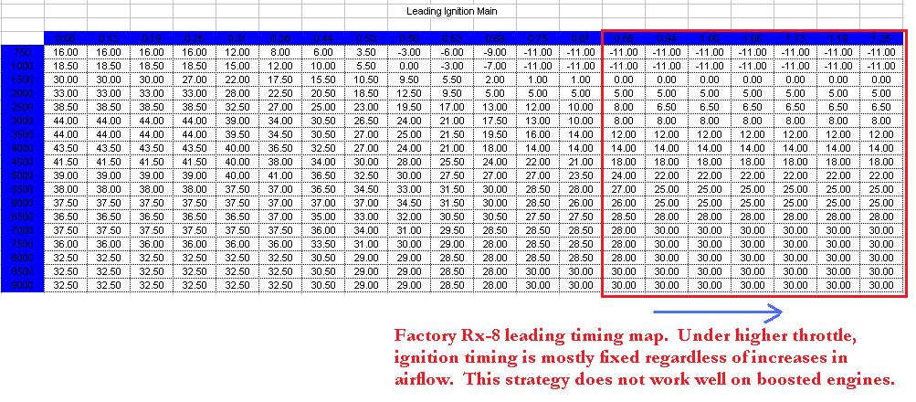
Look horizontally across this map again. Now look at the area I highlighted on the Evo map. Do you see what I mean when I say the factory Rx-8 maps are more "flat" ? Now look at Kane's map.

This map has rescaled load points. But notice how the numbers stay the same when you look across horizontally? By not "ramping" the timing according to changes in airflow, you end up with the ignition timing being too advanced or too retarded in some areas. The result will be a loss of performance or possible engine damage. Now you can see that type of strategy in the factory map posted above, but this is a whole different ballgame here.
Originally Posted by MazdaManiac
Wow. 23� of timing at 6k RPM and 200% load with a 13� split on a "start-up" tune? Adventuresome.
In general, they start come apart around 20� �2� at that RPM on race gas at 10:1 AFR.
In general, they start come apart around 20� �2� at that RPM on race gas at 10:1 AFR.
Last edited by arghx7; 01-02-2010 at 03:58 PM.
The following users liked this post:
rob babicki (07-02-2021)
01-02-2010, 04:05 PM
#18
The generally accepted practice is to decrease timing advance as load increases. However, you must also advance timing as RPM increases and since the flame front speed does NOT universally increase as load increases, simply having a decreasing "ramp" as the load goes up isn't really close to optimal.
The flame goes its fastest at the torque peak and 12.3:1 or so. in any direction you look away from that exact point, the timing should be advanced (given the same load factor).
So, generally, you find optimum torque peak timing at the correct A/F and work your way back up from there.
The flame goes its fastest at the torque peak and 12.3:1 or so. in any direction you look away from that exact point, the timing should be advanced (given the same load factor).
So, generally, you find optimum torque peak timing at the correct A/F and work your way back up from there.
01-02-2010, 04:10 PM
#19
However, you must also advance timing as RPM increases and since the flame front speed does NOT universally increase as load increases, simply having a decreasing "ramp" as the load goes up isn't really close to optimal.
You can see it in the Subaru 3d map I posted:
01-02-2010, 04:14 PM
#20
You can actually calculate a lot of it, but it depends on getting accurate flow information for the entire load range and nailing the fuel down.
Both of which have to be done with timing that wont blow up the motor.
Actually, I'm quite surprised more people don't do the actual timing calculation since it is based on several fixed (or relatively fixed) factors that are known.
Both of which have to be done with timing that wont blow up the motor.
Actually, I'm quite surprised more people don't do the actual timing calculation since it is based on several fixed (or relatively fixed) factors that are known.
01-02-2010, 04:41 PM
#21
The devil made me do it
iTrader: (1)
Join Date: Jul 2007
Location: Colorado Springs, CO
Posts: 3,708
Likes: 0
Received 2 Likes
on
2 Posts
Ok...so basically the rows of the sheet are showing engine RPM's and the cells of the rows are showing what the timing value is from X. So as your RPM's increase you would need to increase your timing so that your plugs fire as the rotor face comes around to the right point...right? Now...RPMs are really easy to comprehend...but what is load...airflow? And if it were airflow the small/little/no change that was made beyond 100% would make sense since he started from base...yes?
01-02-2010, 09:03 PM
#22
Wow - lots of good info guys.... keep in mind that I AM BREAKING IN MY MOTOR... I do not ever intend to hit boost and if I do it is 2-3 PSI max. I thought I had specified that in my post - but apparently did not so I apologize.
This map is a copy of a basemap from another forum member.... I am not paying attention to it right now because I am dialing in my cruise and the moment and have 400 miles left on the break in.
This map is a copy of a basemap from another forum member.... I am not paying attention to it right now because I am dialing in my cruise and the moment and have 400 miles left on the break in.
