DIY: OBD-II Relocation
 03-17-2009, 07:44 PM
#1

DIY: OBD-II Relocation
I'm sure most of you would agree that driving with an OBD-II dongle inserted can be annoying (like with the AccessPort).
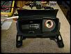
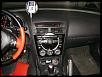
So I decided to move my OBD-II port away from the foot-well area and into the center ashtray (since there is no smoking allowed in my car).
Here is what I did:
1. First disconnect the battery.
There is power going to the OBD-II port at all times (those with the AP know just from turning off the car and the AP is still on).
2. Remove the shift ****
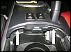
3. Gently pry up the center console using a flat-head screwdriver.
Once you get the rear of the console up, use the screwdriver along the sides to lift the rest of the console up.
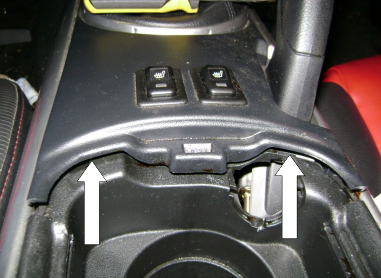
4. Disconnect the harnesses for the heated seats (if applicable).
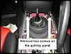
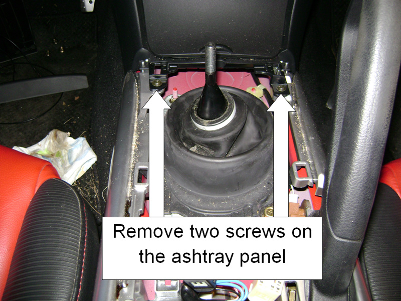
5. Remove the two screws in front of the ashtray panel.
6. Gently remove the ashtray and disconnect the harnesses behind it.
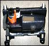
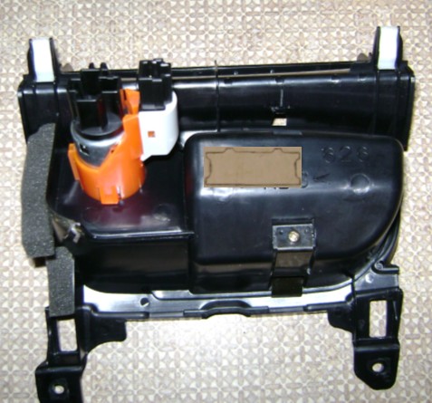
7. Remove the OBD-II port from the bracket.
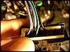
8. Cut each wire leaving enough room on either side to butt-splice later.
9. Cut six 20 or 22 gauge wire to 4-foot lengths.
10. Crimp each side of the wires you just cut with butt-splice connections.
So I decided to move my OBD-II port away from the foot-well area and into the center ashtray (since there is no smoking allowed in my car).
Here is what I did:
1. First disconnect the battery.
There is power going to the OBD-II port at all times (those with the AP know just from turning off the car and the AP is still on).
2. Remove the shift ****
3. Gently pry up the center console using a flat-head screwdriver.
Once you get the rear of the console up, use the screwdriver along the sides to lift the rest of the console up.
4. Disconnect the harnesses for the heated seats (if applicable).
5. Remove the two screws in front of the ashtray panel.
6. Gently remove the ashtray and disconnect the harnesses behind it.
7. Remove the OBD-II port from the bracket.
8. Cut each wire leaving enough room on either side to butt-splice later.
9. Cut six 20 or 22 gauge wire to 4-foot lengths.
10. Crimp each side of the wires you just cut with butt-splice connections.
Last edited by Jon316G; 03-17-2009 at 09:59 PM.
 03-17-2009, 07:45 PM
#2
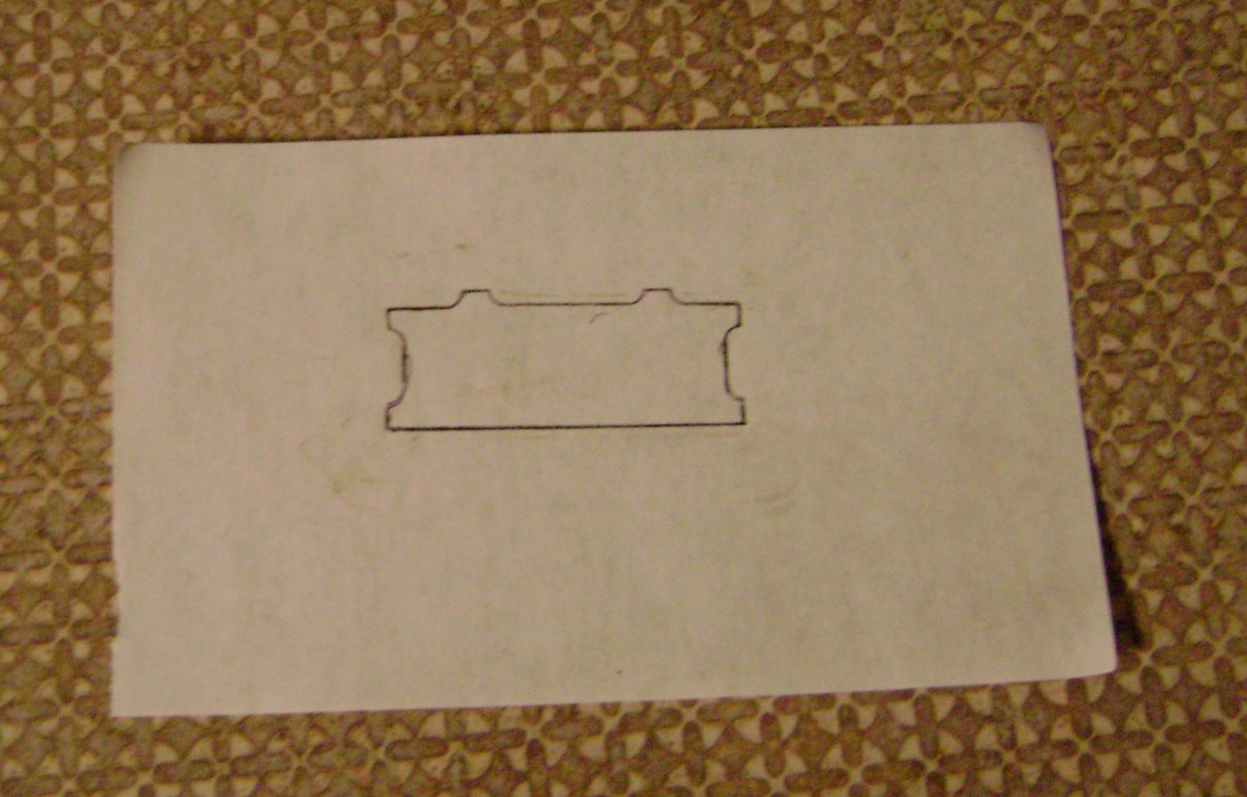
12. Trace an outline of the OBD-II connector from the bracket.
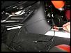
13. Looking at the rear of the ashtray panel, you want the connector to go in the left-most area just above the bottom curve.
This will give you the most clearance (see pic below for an idea of location)
14. Cut the inside area of the stencil outline, lay it in position on the rear of the ashtray panel, and fill in the area with a sharpie.
15. Then carefully cut out the area you filled in. Take your time and take small cuts off, don't want to take off too much.
16. Snap the connector into place through the rear of the ashtray panel.
17. Run all your wires (cut to 4' lengths) through the center (under the radio unit) and out the side.
I used a snake to make it easier, but a coat hanger works too.
18. Butt-Splice the piggy-back wires on the back of the ashtray panel and wrap with electrical tape.
19. Label the other end of each extension wire with the corresponding wire color code from the OBD-II connector (ex: blue wire with red strip, or I wrote BU/RD... long as you know what the color is).
I used blue painter's tape and wrapped a strip around the wire.
20. Reinstall the ashtray panel and center console.
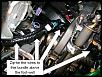
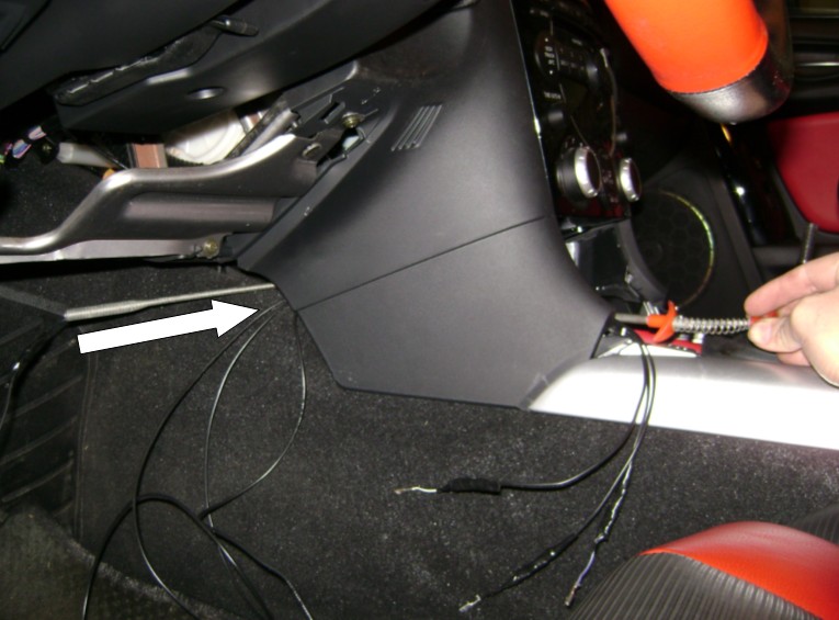
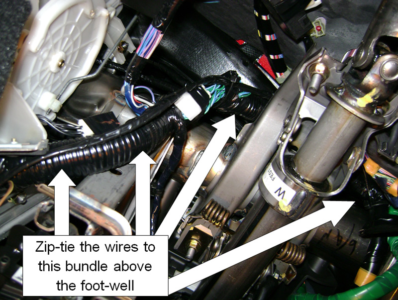
21. Zip-tie the wires around the steering column, following the wire loom.
13. Looking at the rear of the ashtray panel, you want the connector to go in the left-most area just above the bottom curve.
This will give you the most clearance (see pic below for an idea of location)
14. Cut the inside area of the stencil outline, lay it in position on the rear of the ashtray panel, and fill in the area with a sharpie.
15. Then carefully cut out the area you filled in. Take your time and take small cuts off, don't want to take off too much.
16. Snap the connector into place through the rear of the ashtray panel.
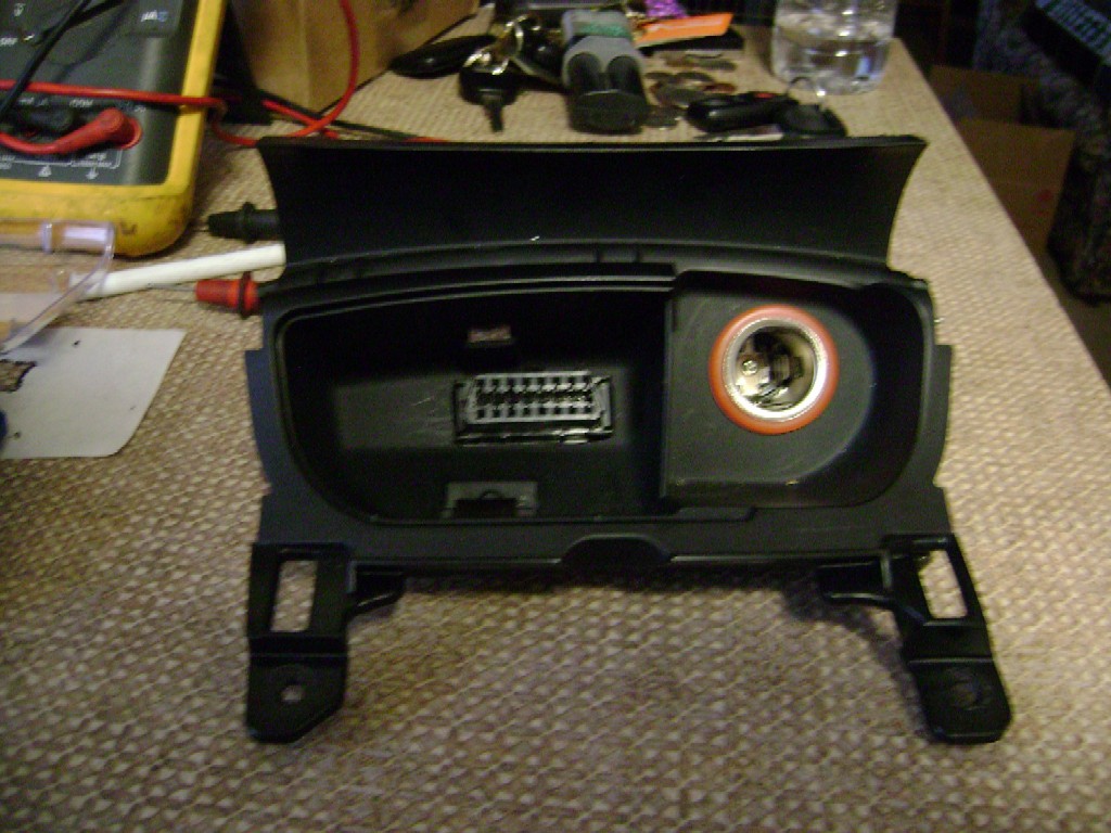
17. Run all your wires (cut to 4' lengths) through the center (under the radio unit) and out the side.
I used a snake to make it easier, but a coat hanger works too.
18. Butt-Splice the piggy-back wires on the back of the ashtray panel and wrap with electrical tape.
19. Label the other end of each extension wire with the corresponding wire color code from the OBD-II connector (ex: blue wire with red strip, or I wrote BU/RD... long as you know what the color is).
I used blue painter's tape and wrapped a strip around the wire.
20. Reinstall the ashtray panel and center console.
21. Zip-tie the wires around the steering column, following the wire loom.
Last edited by Jon316G; 03-17-2009 at 10:15 PM.
03-17-2009, 07:45 PM
#3
22. Butt-splice the other end of your 4' extension wires to the correct wires in the foot-well where the OBD-II port was (Hopefully you labeled each wire as mentioned before).
If you didn't label the other end, you'll need to remove the ashtray panel and do a continuity test to verify what each wire is).
23. Wrap the connections with electrical tape.
24. Zip-tie any excessive wire out of the way so no wires are dangling.
25. Reconnect battery and cross your fingers while inserting your AccessPort (or any other reader).
Last edited by Jon316G; 03-17-2009 at 10:32 PM.
 03-17-2009, 09:39 PM
#6
Certified Mazda Tech
why push the pins out? why not cut the obd2 connector with pigtails sticking out, that way no need to potentially mix up which goes where, then cut enough wires to length, pass them all through with butt connectors already on. Match wire color from obd2 pigtail to harness, insert jumper wire.
If you wanted to use less butt connections (which have a tendency to sometimes raise resistance, and you always want to limit new circuit conditions) then I'd reccommend getting all new pins, solder a length of wire to the stock harness then attach the new pin to that wire and insert into the proper spot on the obd2 connector, that'd be the best and longest lasting way, although i probably would've just done it your way too.
kevin.
03-17-2009, 09:46 PM
#7
why push the pins out? why not cut the obd2 connector with pigtails sticking out, that way no need to potentially mix up which goes where, then cut enough wires to length, pass them all through with butt connectors already on. Match wire color from obd2 pigtail to harness, insert jumper wire.
You're right, I think I originally did that because I was going to use the back of the connector to draw-out the stencil outline, but decided to just use the opening in the bracket instead.
I might have to re-write that part... thanks.
If you wanted to use less butt connections (which have a tendency to sometimes raise resistance, and you always want to limit new circuit conditions) then I'd reccommend getting all new pins, solder a length of wire to the stock harness then attach the new pin to that wire and insert into the proper spot on the obd2 connector, that'd be the best and longest lasting way, although i probably would've just done it your way too.

I was actually going to do this, but knowing that some people here (on this forum) might shy away from this mod when they see soldering and needing to crimp the pins, I decided to do something that even the most novice person could do (or make it as easy as possible).
03-17-2009, 09:53 PM
#8
Certified Mazda Tech
Great minds think alike
I was actually going to do this, but knowing that some people here (on this forum) might shy away from this mod when they see soldering and needing to crimp the pins, I decided to do something that even the most novice person could do (or make it as easy as possible).
I was actually going to do this, but knowing that some people here (on this forum) might shy away from this mod when they see soldering and needing to crimp the pins, I decided to do something that even the most novice person could do (or make it as easy as possible).
nice writeup overall.
kevin.
08-17-2009, 01:08 AM
#10

Or you could buy a pigtail and the car side plug from here for about $15 and make your own extension harness.....no hastles with cutting and soldering a databus
http://www.bmotorsports.com/shop/ind.../cPath/109_151
http://www.bmotorsports.com/shop/ind.../cPath/109_151
08-17-2009, 01:23 AM
#12

Lots of good options here too.
http://www.obd2cables.com/products/o...ii-cables/?p=2
I like the ones with the 90 deg angle. Would improve clearance I think.
http://www.obd2cables.com/products/o...ii-cables/?p=2
I like the ones with the 90 deg angle. Would improve clearance I think.
07-25-2011, 08:49 PM
#14
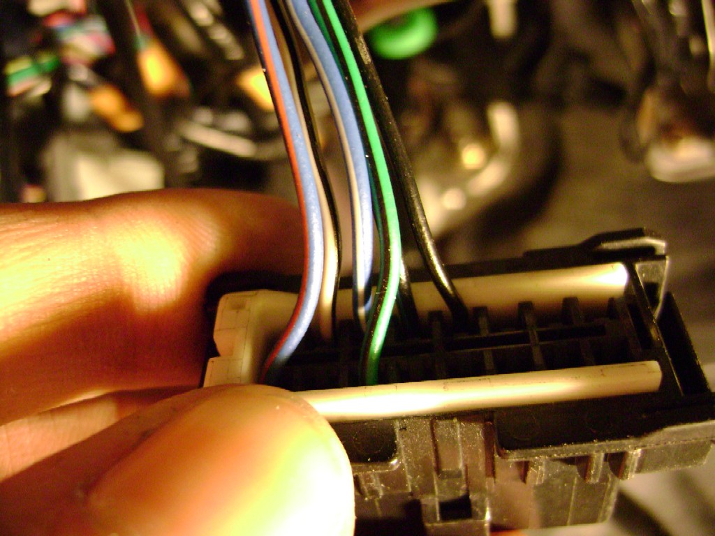
Its the blue wire with a red stripe and at the corner of the port.
After that... the USB cable... then the AP itself.
The voltage is coming from the 15A ROOM fuse, which is also shared with many other components... so may not be that unless your radio isn't working also.
EDIT: OH... and the pins on the dongle... could be pushed-in or not making contact.
Can't believe I forgot that one since that was the purpose of this thread:
https://www.rx8club.com/series-i-do-yourself-forum-73/diy-making-better-obd-ii-connection-ap-dongle-169724/
Last edited by Jon316G; 07-25-2011 at 08:56 PM.
07-25-2011, 09:37 PM
#15
Registered

Join Date: Jul 2010
Location: Huntington Beach, CA
Posts: 87
Likes: 0
Received 0 Likes
on
0 Posts
Voltage to the OBD-II port!
Its the blue wire with a red stripe and at the corner of the port.
After that... the USB cable... then the AP itself.
The voltage is coming from the 15A ROOM fuse, which is also shared with many other components... so may not be that unless your radio isn't working also.
EDIT: OH... and the pins on the dongle... could be pushed-in or not making contact.
Can't believe I forgot that one since that was the purpose of this thread:
https://www.rx8club.com/showthread.php?t=169724
it should be the fuse, my head unit is not working, my footwell light is also not working. my window is also not working at the moment, i installed a tr-7 for auto close and open using the remote key, but the autoshop that repainted my car manage to mess up with my wiring.
somewhat similar to this thread ( https://www.rx8club.com/showthread.p...ad+unit&page=2 )
i hope it just the fuse though, im worried the head unit was fried.

Thread
Thread Starter
Forum
Replies
Last Post
Shankapotamus3
Series I Trouble Shooting
28
03-14-2021 03:53 PM
05rx8mazda
RX-8 Parts For Sale/Wanted
18
11-28-2015 09:42 AM