New patents for Mazda rotary released!
 12-16-2010, 01:59 AM
#1
Registered User
Thread Starter

Join Date: Oct 2007
Posts: 5
Likes: 0
Received 0 Likes
on
0 Posts
New patents for Mazda rotary released!
I regulary check for new mazda patents related with rotary engines. There are few new just if someone is interested...
New lubrication system (P.No.JP2010174740A):

Direct injection with oversize hole for using compressed air from compresion chamber (P.No.JP2010156292):

New trailing plug with plasma jet ignition (P.No.JP2010156291A):
Dual injectors for direct injection (P.No.JP2010156289):

Best regards,
Mike
New lubrication system (P.No.JP2010174740A):

Direct injection with oversize hole for using compressed air from compresion chamber (P.No.JP2010156292):

New trailing plug with plasma jet ignition (P.No.JP2010156291A):
Dual injectors for direct injection (P.No.JP2010156289):

Best regards,
Mike
 12-16-2010, 02:07 AM
#2
Registered User

Join Date: Nov 2010
Posts: 6
Likes: 0
Received 0 Likes
on
0 Posts
I regulary check for new mazda patents related with rotary engines. There are few new just if someone is interested...
New lubrication system (P.No.JP2010174740A):

Direct injection with oversize hole for using compressed air from compresion chamber (P.No.JP2010156292):

New trailing plug with plasma jet ignition (P.No.JP2010156291A):
Dual injectors for direct injection (P.No.JP2010156289):

Best regards,
Mike
New lubrication system (P.No.JP2010174740A):
Direct injection with oversize hole for using compressed air from compresion chamber (P.No.JP2010156292):
New trailing plug with plasma jet ignition (P.No.JP2010156291A):
Dual injectors for direct injection (P.No.JP2010156289):
Best regards,
Mike
12-16-2010, 08:50 AM
#3
Rotared
iTrader: (1)

Join Date: Sep 2005
Location: SW OKC
Posts: 215
Likes: 0
Received 0 Likes
on
0 Posts
What is interesting is the new OMP. It looks like there are several pumps to lubricate different amounts to the center of the housing and the edges of the housings where flaking occurs. This should help w/ lubricating the apex seals and the wear they see.


 12-16-2010, 09:50 AM
#8

I'm having trouble finding these patents. Are you sure these are the right numbers? I'm on google and appft.uspto.gov but nothing is coming up with those numbers
Last edited by arghx7; 12-16-2010 at 10:06 AM.


 12-16-2010, 05:01 PM
#18
Registered User
Thread Starter
Join Date: Oct 2007
Posts: 5
Likes: 0
Received 0 Likes
on
0 Posts
Patent numbers:
JP2010174740A
JP2010156292A
JP2010156291A
JP2010156289A
I find them with gb.espacenet.com searching all patents from mazda (advanced search)
Insert patent number here:
http://gb.espacenet.com/search97cgi/.../en/number.hts
JP2010174740A
JP2010156292A
JP2010156291A
JP2010156289A
I find them with gb.espacenet.com searching all patents from mazda (advanced search)
Insert patent number here:
http://gb.espacenet.com/search97cgi/.../en/number.hts
12-16-2010, 05:30 PM
#19
^ Thanks! That's a big help. Unfortunately the patents are indeed in Japanese. But we can at least look at the pictures. From the JP2010156289 patent on the dual injector design:
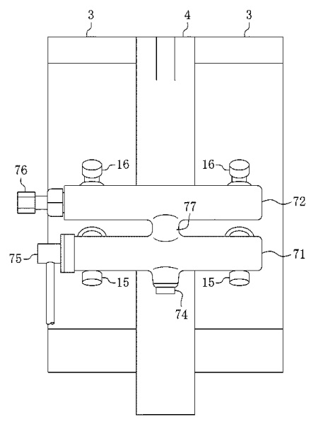
This looks like a sketch of the fuel rails and injector positioning on top of the rotor housings. Both injectors are in the rotor housing. The abstract is in English so we can see how the injection works:
It is common on direct injected engines to inject during the compression stroke under low load but not during high load. VW engines are like that. Under low load I bet the intake-side injector sprays only a small amount of fuel.
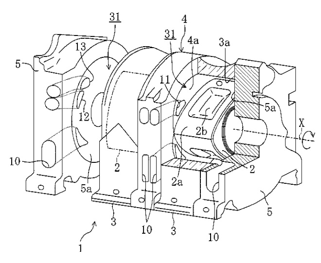
In this diagram we can see this is a 6 port engine like the protype displayed a few years ago, meaning it is most likely naturally aspirated. There is also what looks like an injection timing diagram (see attached) of the sort Mazda published for previous engines.
This looks like a sketch of the fuel rails and injector positioning on top of the rotor housings. Both injectors are in the rotor housing. The abstract is in English so we can see how the injection works:
The rotary piston engine 1 is provided with a first fuel injection valve 15 and a second fuel injection valve 16. The first fuel injection valve 15 directly injects fuel into the working chamber 8 which is in an intake stroke, and the second fuel injection valve 16 directly injects fuel into the working chamber 8 which is in a compression stroke. A control means 100 performs intake stroke injection by the first fuel injection valve 15 when the operating condition of the engine 1 is in the heavy load operation area, and performs fuel injection during the intake stroke by the first fuel injection valve 15 and fuel injection during the compression stroke by the second fuel injection valve 16 when the operating condition of the engine 1 is in the partial load operation area.
In this diagram we can see this is a 6 port engine like the protype displayed a few years ago, meaning it is most likely naturally aspirated. There is also what looks like an injection timing diagram (see attached) of the sort Mazda published for previous engines.
Last edited by arghx7; 12-16-2010 at 05:37 PM.
 12-16-2010, 06:16 PM
#22
So this plasma ignition patent is unusual. From some searching, apparently plasma ignition has been in research labs for a long time but I don't think it has ever been used on a production engine for a passenger car. From what I can tell, somehow the plug creates ionized gases which are sent into the air/fuel mixture to trigger ignition with a cleaner burn.
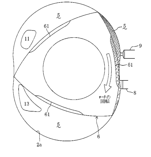
The upper shaded area appears to be the portion of the combustion chamber that will be burned by the plasma ignition system under low loads. NGK recently filed a patent (also in Japanese) for a plasma-jet ignition plug. http://www.sumobrain.com/patents/wip...010073609.html . You can see some drawings of it. At first glance they don't physically appear much different from regular spark plugs to me.
In addition to the altered combustion chamber dimensions, could the plasma ignition and dual direct injection design be Mazda's strategy for improving highway mileage and other low load driving efficiency?
The ignitability and the ignition stability are sufficiently enhanced by igniting an air-fuel mixture by a plasma jet of high energy, in a plasma jet ignition area P on a relatively low-load and low-rotation side. Plasma jet ignition is carried out in the T-side ignition plug affecting the ignition stability, and spark ignition is carried out in the L-side ignition plug, particularly in a prescribed area in a low load side, so as to restrain the consumption of an electrode of each ignition plug. Spark ignition is carried out in both the L-side ignition plug and the T-side ignition plug, in a spark ignition area S within a high-load or high-rotation area
The upper shaded area appears to be the portion of the combustion chamber that will be burned by the plasma ignition system under low loads. NGK recently filed a patent (also in Japanese) for a plasma-jet ignition plug. http://www.sumobrain.com/patents/wip...010073609.html . You can see some drawings of it. At first glance they don't physically appear much different from regular spark plugs to me.
In addition to the altered combustion chamber dimensions, could the plasma ignition and dual direct injection design be Mazda's strategy for improving highway mileage and other low load driving efficiency?
12-16-2010, 06:18 PM
#23
Administrator

if you go here http://www4.ipdl.inpit.go.jp/Tokujit...ipdl?N0000=115
in put an a for the "kind code" and the number formatted like this 2010-156292 you can get a bit of a translation
in put an a for the "kind code" and the number formatted like this 2010-156292 you can get a bit of a translation
 12-16-2010, 07:03 PM
#25
Administrator
these, excepting the oiling- were developed on the hydrogen engine and adapted for the 16x.
some of the early plasma jet ignition work was done using hydrogen as the source for the plasma
http://www.docstoc.com/docs/45898437...Patent-4471732
some of the early plasma jet ignition work was done using hydrogen as the source for the plasma
http://www.docstoc.com/docs/45898437...Patent-4471732